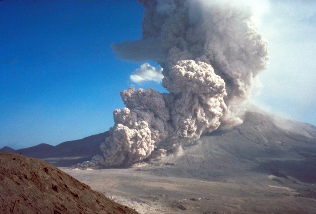
This post continues the series on volcanic and volcaniclastic rocks in outcrop, with a brief introduction to pyroclastic density currents (PDCs).
It has become cliché to describe pyroclastic flows as hazardous to one’s health. I prefer a more colourful analogy found in a rewording of Tolkien’s description of the fire-breathing dragon Smaug the Terrible, voiced by Bofur the dwarf as “a flash of light, searing pain, and poof! You’re nothing more than a pile of ash.” – an analogy that paints a picture of instant incineration, laceration, and suffocation if confronted by a maelstrom of hot gas and razor-sharp fragments of volcanic glass. Distinctly unpleasant.
Pyroclastic density current (PDC) is the catch-all term to describe ground-hugging, gravity-driven mixtures of gas and volcaniclastic debris, derived from explosive eruptions. PDCs are fast moving (several 10s to 100s of km/hour), and invariably warm (up to 700o C – 1300oF). The term encompasses pyroclastic flows, ignimbrites, block and ash flows, pyroclastic surges, and base-flows (but not lahars). They all consist of fragmented, most commonly silicic magma, vent wall-rock, and ripped up substrate. They are two-phase systems, like much colder sediment gravity flows such as turbidity currents and debris flows, except the fluid phase in PDCs is a mix of water vapour, ingested air, and probably some CO2. Recent PDCs are mostly generated by explosive magmatic eruptions, but they are also known from violent phreatomagmatic events such as maar eruptions.
Our understanding of pyroclastic flows, their internal organisation, mechanisms of emplacement, and how these variables evolve as the flow progresses, is seriously hampered by our inability to get close enough for observation and measurement. We can establish their external organisation and geometry from direct observations (from afar) and videos of relatively small, recent flow events. Flow stratigraphy gives us snapshots in time of processes at the depositional surface, but not in the overlying flow. Numerical modelling can fill some of these knowledge gaps, but models also rely on real data for meaningful calibration.
However, all is not lost. Volcanologists have unashamedly borrowed (and subsequently modified) some well-established observational data and theory from our knowledge of ‘cold’ sediment gravity flows (i.e., turbidite currents, debris flows, and grain flows). Our understanding of sediment gravity flow mechanics has advanced from direct observation of cold flow events, a century of analogue modelling (e.g., flumes), plus conceptual and numerical models. We tend to think of support mechanisms in sediment gravity flows in terms of turbulence or laminar flow, matrix strength and viscosity (i.e., fluid rheology – is it acting like a hydroplastic or Newtonian fluid?), collisions among grains, buoyancy, and shear forces acting near the flow-substrate contact. These are all properties and processes that can be applied to models of pyroclastic flows, with the added complication of elevated temperature. Significantly, the last couple of decades have also seen the development of (cold) flume-like pyroclastic flow experiments in air, using volcanic granular material to simulate the characteristics of flow and the resulting stratigraphy (e.g., Lube et al., 2015; PDF available). Laser technology also provides us with the opportunity to look inside these experimental flows, to track particle trajectories along their journey from flow initiation to deposition.
Flow initiation
All pyroclastic flows are initiated by explosive eruptions from subaerial volcanic cones, maars, and collapsing calderas (see the diagram below). It is common for more than one mechanism to operate during an eruption episode (Belousov et al., 2007; PDF available). This was demonstrated by the 1980 Mt. St. Helens activity that showed us, perhaps more than any other recent event, that eruption mechanisms can evolve rapidly and devastatingly – in this case, from an initial upper-flank collapse and subsequent landslide to magma dome collapse that released a directed, lateral pyroclastic blast, and later collapse of plinian eruption columns.
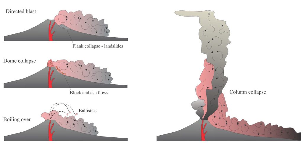
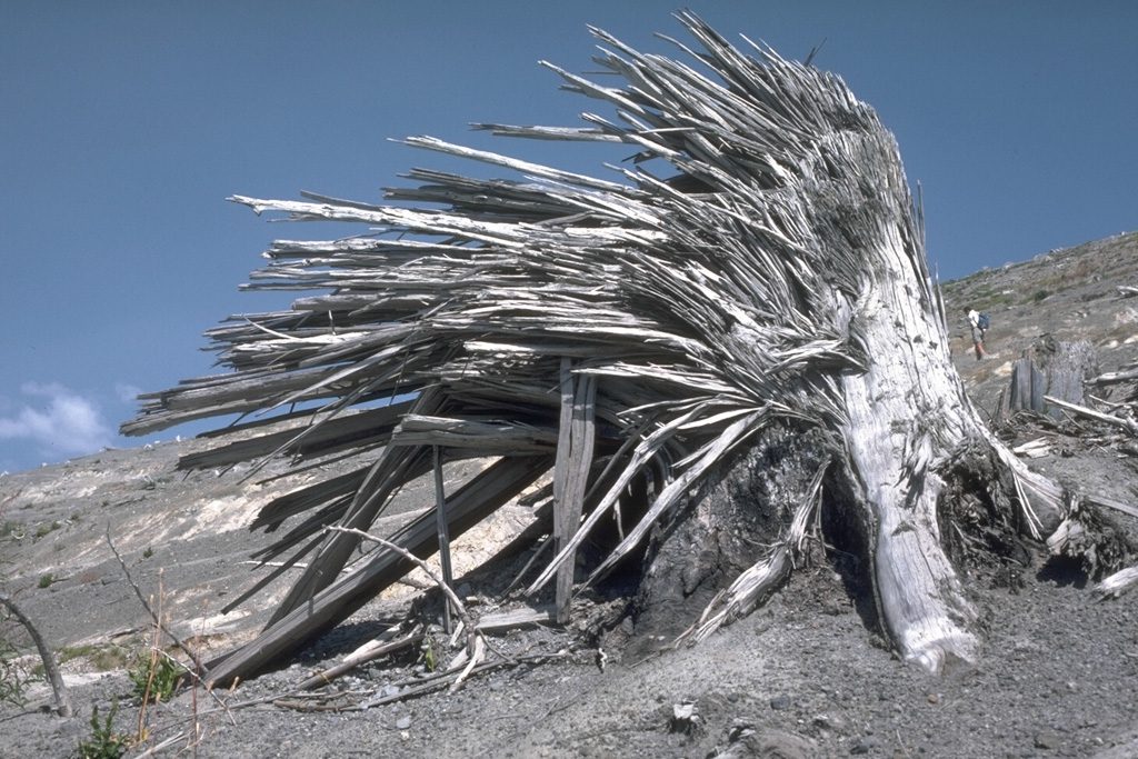
Silicic domes that protrude from the crater or upper flank of a volcanic edifice grow relatively slowly by accretion of magma. The domes act like a pressure valve; they are inherently unstable gravitationally and because of elevated pressures. Breaching the valve (dome collapse) will release a blast of gas plus fragmented magma and cooled rock. Blasts that are directed laterally transform rapidly to pyroclastic flows. Recent examples are Mt. St. Helens and Soufriere Hills; both eruption episodes also included vulcanian and plinian columns that collapsed to produce pyroclastic flows. Directed blasts are usually associated with flank, sector, or magma dome collapse; flank collapse will also produce landslides. Initial blast velocities can be more than 350 km/hr.
The boil over category refers to fountain ejection of fragmented magma over a crater rim. Little or no fragmental debris is supplied by plume collapse. Lava fountains produce all manner of ballistic melt ejecta that on impact form breadcrust and cow-pat bombs. PDCs formed from this material are concentrated in various kinds of ejecta.
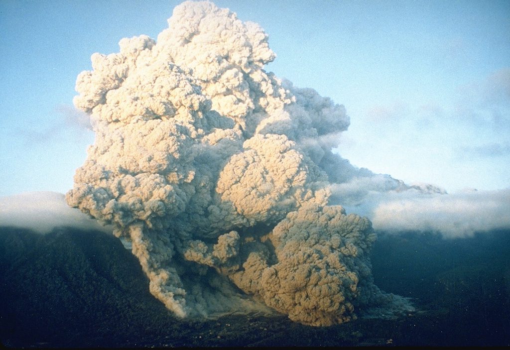
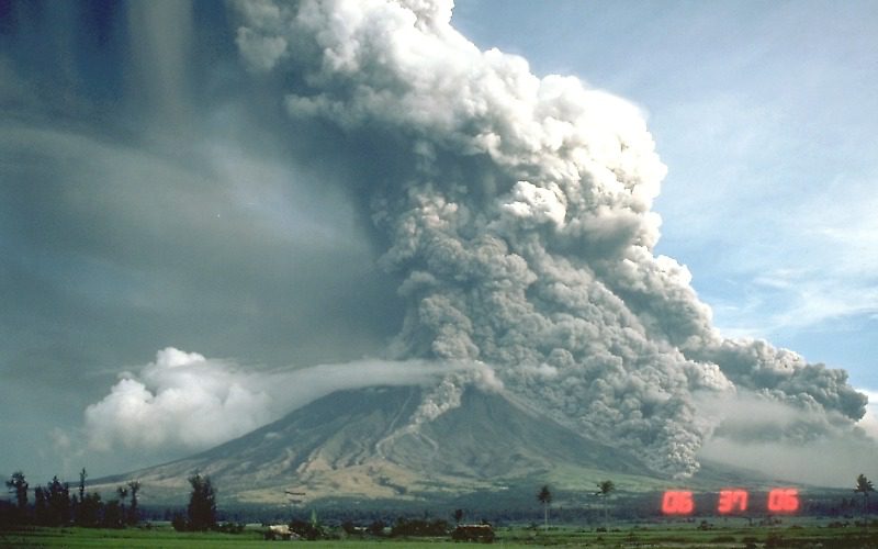
PDCs are also generated by column collapse when gravitational forces exceed the buoyancy of ash-rich ejecta. The size and runout of PDCs formed in this way depends on the size of the eruption column. Several PDCs can form at any time during an eruption, as new plumes form and earlier plumes collapse. The image of Mayon Volcano below (Sept. 23, 1984) shows at least 5 concurrent PDCs at different stages of development; the plume in this eruption reached an elevation of 15 km.
Parts of a flow – Inside PDCs
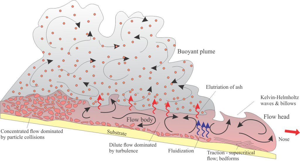
PDCs consist of two main components:
- The main, ground-hugging body of the flow, which is denser than air, and
- An overlying buoyant plume, less dense than air, that grows as fine ash elutriates from the main body of the flow.
The flow head is differentiated from the main body by the abrupt boundary between air and the billowing, turbulent mixture of gas and fragmental debris. Typically, the nose of the flow lifts above the substrate because friction along the substrate reduces the velocity relative to the overlying flow. This is also a common feature of cold sediment gravity flows (e.g., turbidity currents). Any erosion of the substrate probably takes place beneath the head.
The flow body is overlain by a buoyant plume. Some erosion may occur at the base but this part of a flow tends to be constructional because of sedimentation.
Particle concentration is highly variable among different PDCs and within a single PDC. Two end-member conditions, commonly defined as dilute flows (in which turbulence is the primary supporting mechanism) and concentrated flows (dominated by grain-to-grain collisions), are useful starting points for a description of PDCs. The concentration profile of a PDC may indicate either condition, or combinations where a basal layer contains high fragment concentrations overlain by a more dilute flow. Some flows retain their concentrated profiles throughout; deposition of coarse debris along levees is common on the margins of such flows. In other PDCs, fragment concentration profiles change in the down-flow direction because the ingestion of air through the billowing flow-top in addition to particle deposition will both promote dilution.
Pyroclastic surges are typically dilute. A flow may begin life as a pyroclastic surge if initial particle concentrations are low, or it may evolve by progressive dilution of more concentrated flows. Sedimentation commonly involves bedload processes under supercritical flow conditions, resulting in a variety of low amplitude crossbeds and crossbed truncations.
Flow support mechanisms
Propagation of PDCs will continue only as long as there is a mechanism to support the suspension of fragmental debris. The most common mechanisms are turbulence, particle collisions, and fluid pressure and fluidization.
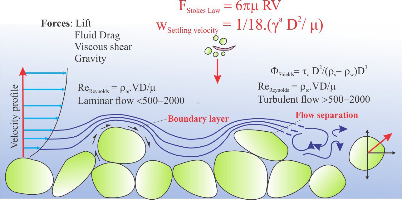
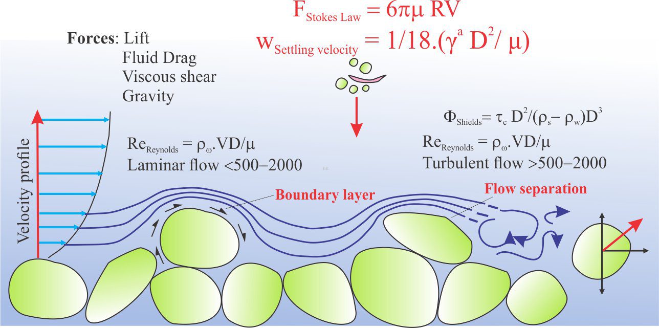
The development of turbulent flow is probably initiated immediately flow begins because velocities are high and viscosity is low (i.e., very high Reynolds Numbers). In dilute flows, turbulence will also be generated at the base of the flow because of substrate roughness (e.g. boulders that stand out), and by abrupt changes in topography. It has also been observed that near the flow head, intense shear at the contact between the rapidly moving flow and overlying air and will lead to Kelvin-Helmholtz instabilities, resulting in elutriates and billows; instabilities may also form at the contact between the body of a flow and its overlying buoyant plume. This transformation is analogous to the more familiar atmospheric Kelvin-Helmholtz waves, commonly manifested as mackerel skies and the gut-wrenching turbulence during air travel. The unstable boundary rapidly transforms to turbulence that promotes the ingestion of air into the flow body.

As flows progress, suspended fragments will lose momentum and become more concentrated near the flow base. Thus, flows become progressively more dilute and at some point, the mixture of gas and fine particles will become less dense than air, resulting in a buoyant plume above the main flow.
In the more concentrated parts of a flow, particularly at the base, interparticle collisions result in the transfer of momentum that helps to support the flow. However, each collision also results in the transfer of some kinetic energy to the gas phase; the gradual loss of momentum leads eventually to deposition.
Elevated fluid pressures (air plus water vapour) and will also play a role in supporting solid debris in the main body of a flow (pressure gradients will be directed from bottom to top). Incinerated vegetation and vapourized soil moisture may increase local fluid pressures at the flow base. The system will become fluidized if upwards fluid flow exceeds the gravitational forces acting on particles. Particles will fall out of fluid suspension once the elevated pressures have dissipated.
Evidence for post-depositional elevated fluid pressures is sometimes preserved as fluid escape pipes, which form where permeability barriers in the deposits cause local overpressured conditions.
At the depositional interface
Volcanologists consider two end-member modes of deposition for PDCs – en masse freezing of the entire flow body, and incremental deposition on an aggrading bed. There is still debate over the relative importance of either mechanism.
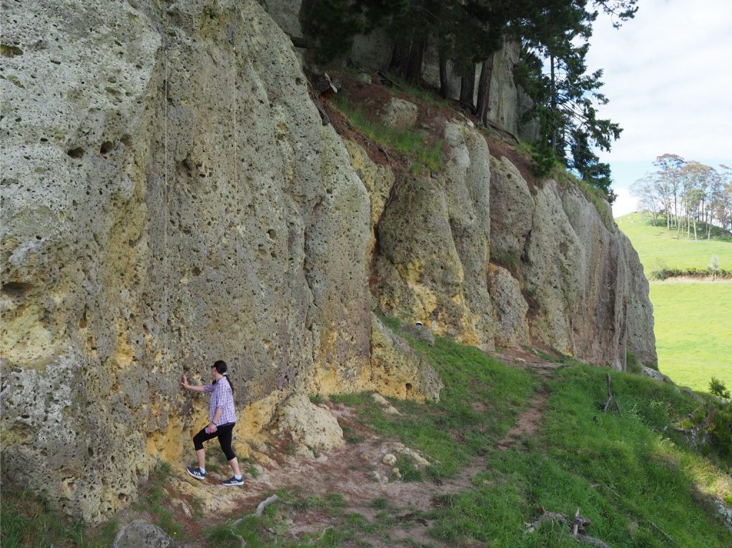
The depositional record of PDCs is as variable as the flows themselves. Deposits may be massive, lacking any kind of stratification, massive but clast-size graded, stratified, or combinations that reflect changing particle concentrations and mechanisms of flow.
Massive deposits are perhaps the most difficult to interpret. Deposits like this may have formed by rapid deposition where turbulent sorting and grain entrainment were suppressed. However, if normal size grading is present, then turbulence has not been suppressed. Reverse grading, particularly of large pumice fragments, indicates that buoyancy forces were also important.
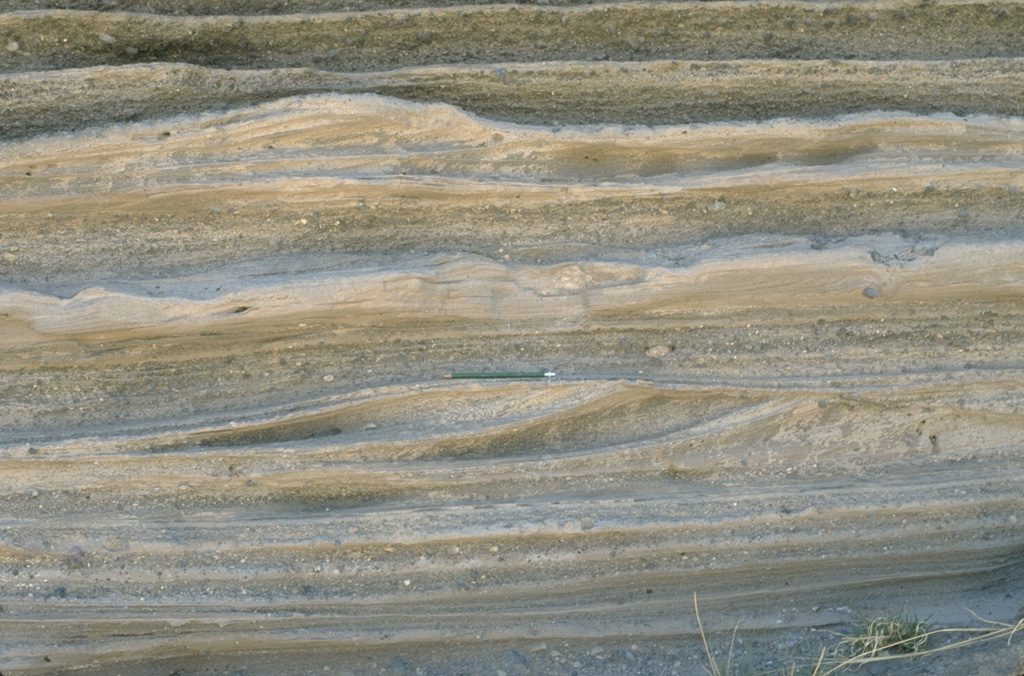
Stratification of any kind within a PDC implies that the forces of shear, friction, and fluid drag were operating along or close to the depositional surface. Processes that lead to bedload deposition include:
- A traction carpet where grains roll, slide and jostle along the bed at a rate depending on flow velocity, fluid drag, and bed roughness (i.e., how many large bits get in the way), and
- A saltation load, where fluid lift provides enough force for grains to temporarily leave the bed.
Stratified bedload deposits are relatively common in dilute PDCs where there is a constant supply of fragments falling out of the overlying turbulent suspension. Deposit thickness depends on the overall particle concentration and size of a flow. Low amplitude crossbeds and crossbed truncations appear to be a hallmark of pyroclastic surges. It is usually concluded that these bedforms develop under supercritical flow conditions given the inevitable high velocities of flow.
Related posts
Accretionary aggregates and accretionary lapilli
Ignimbrites in outcrop and thin section
Volcanics in outcrop: Secondary volcaniclastics
Volcanics in outcrop: Lava flows
Volcanics in outcrop: Pyroclastic fall deposits
Fluid flow: Froude and Reynolds numbers
Sediment transport: Bedload and suspension load
The hydraulics of sedimentation: Flow regime
A few sources of information
Excellent sources of PDC images available from the Smithsonian Institution gallery, and the USGS gallery.
Dufek et al., 2015 (PDF)Pyroclastic density currents: Processes and models. Chapter 35. An excellent summary.
Sulpizio et al., 2016. Pyroclastic density currents: state of the art and perspectives. Journal of Volcanology and Geothermal Research, Vol 283, Pages 36-65.
Giordano and Cas, 2021. Classification of ignimbrites and their eruptions. Earth Science Reviews, v 220, p.
