Sandbox analogue models of strike-slip basins and pop-up structures
How things have changed. It wasn’t that long ago that numerical and analogue structure and stratigraphy models were considered an interesting, sometimes useful add-on to empirical and theoretical studies. Now they are almost de rigueur, and for good reason. Both model methods provide unique views of the processes involved in rock deformation and stratigraphic architecture, so long as we account for model scaling and imposed boundary conditions.
The focus in this post is strike-slip analogue models, but the experimental methods, apparatus, and Earth materials can be used in any deformation analogue modeling.
Strike-slip structural domains
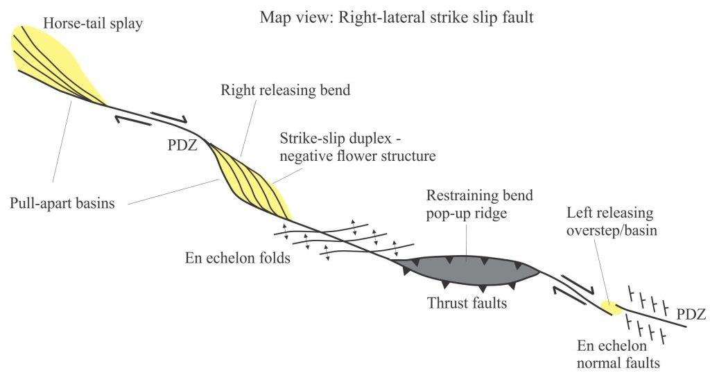
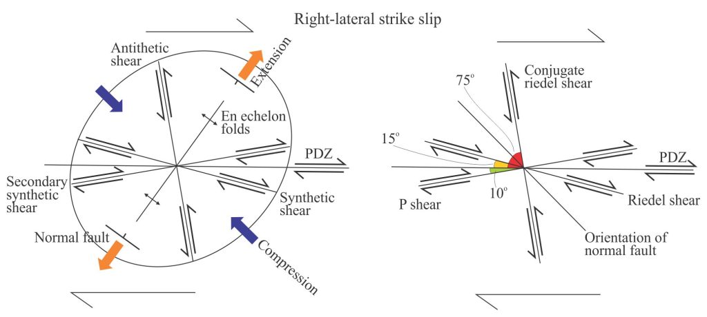
Deformation along a strike slip fault, or strike-slip – transform fault zone usually occurs at fault bends or splays in the principal deformation zone (PDZ). Deformation is manifested as dip-slip and strike-slip fault splays (for example flower structures), secondary faults that are synthetic and antithetic to the PDZ, en echelon folds, uplifts at restraining bends, and pull-apart basins at releasing bends (see the seminal paper by John Crowell, 1974 on the San Andreas transform fault, and the SEPM volume edited by Biddle and Christie-Blick, 1985 for excellent descriptions). The general disposition of these structures and the stress-strain relationships amongst them are well documented from modern and ancient strike-slip domains.
Analogue models of strike-slip faults
There is now a broad selection of published models that represent variations on the general strike-slip theme:
- Models with single and multilayered stratigraphy.
- Models with strong and weak layers such as sandstone – shale (e.g., Zwaan et al, 2022, OA).
- Models with basal ductile layers representing salt, or the basal crust – upper mantle transition (e.g., Smit et al., 2008, PDF).
- Models representing pure strike-slip, transtension and transpression (e.g., Gabrielsen et al., 2023, PDF).
- Models with evolving plate trajectories (strike-slip, extension, contraction – e.g.,Farangitakis et al., 2023, PDF).
Four examples that are representative of these model types are summarized in the following table.
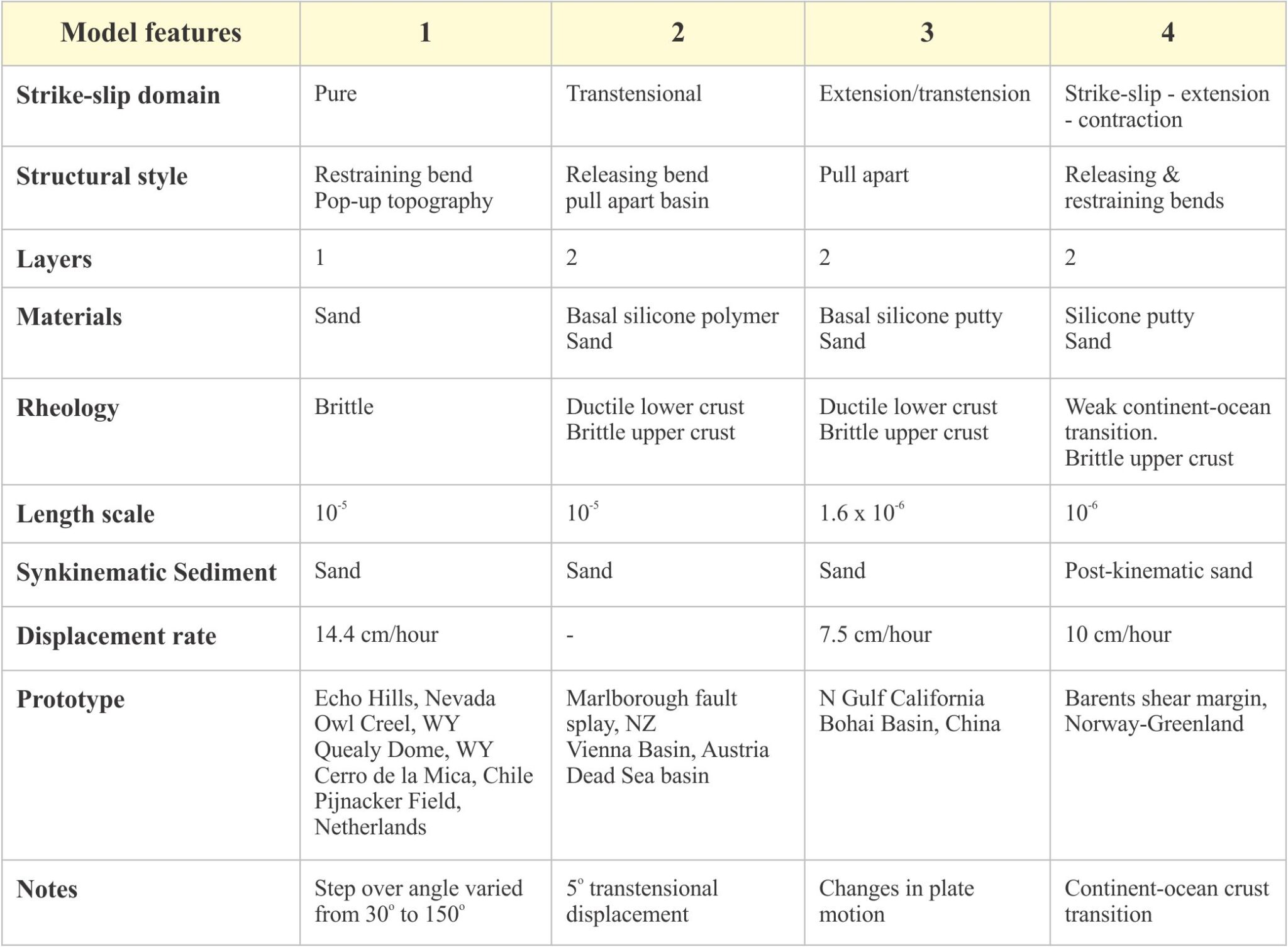
Model 1: McClay and Bonora, 2001.
Model 2: Wu et al., 2009.
Model 3: Farangitakis et al., 2020, op cit.
Model 4: Gabrielsen et al., 2023, op cit.
I have chosen two published examples that are excellent representatives of basic strike-slip fault kinematics and basin formation: Pop-up topography formed during pure strike-slip restraining bend deformation (McClay and Bonora, 2001), and pull-apart basin formation during transtensional displacement (Wu et al., 2009) – model items 1 and 2 respectively in the table above.
Model apparatus
The sand box designs used today for structural analogue experiments are little different from those constructed by Cadell (1889, PDF) and Willis (1894, PDF) – rectangular, open-topped boxes with movable and/or fixed basal plates, and movable or fixed walls. The moving parts are usually driven by simple worm screws, that in modern experiments are computer controlled such that displacement and deformation rates can be varied and monitored accurately.
The geometry of the boundary between movable and fixed base plates predetermines the style of deformation produced. For example, in strike-slip systems, releasing and restraining fault step-overs are built into the contact between the two plates. The boundary in the Gabrielsen et al., model (diagram below) represents the transition between continental and oceanic crust – the boundary geometry determines the structural response to the stress regimes they impose on the model.

The choice of materials filling the boxes depends on the rheological behaviour being examined:
- Dry sand represents brittle behaviour.
- Silicone putty represents ductile behaviour (flow, folding), for example salt layers, or ductile lower crust – upper mantle lithologies.
- PDMS (a more fluid silicone polymer than the putty) or syrup can also be used to represent ductile flow.
- Sand mixed with PDMS (also called kinetic sand) will produce materials that are slightly more cohesive (viscous) and ductile than dry sand.
The layering order and thickness in which different materials are added to a sand box is also a strong determinant of structural style. For example, a single layer of sand will demonstrate only brittle failure, whereas interlayered sand and kinetic sand or silicone putty will also produce stretching or folding. Silicone putty is usually laid as a sheet. Dry sand is added by sieving to ensure an even distribution. Sand is commonly added to the top of the model as deformation progresses to represent synkinematic (syntectonic) sedimentation. Coloured sand layers are used as stratigraphic and structural markers. Markers can also be added to the model surface in grid patterns to provide real-time views of deformation and kinematic pathways.
Experiments are concluded by saturating the materials with a water-soluble gel so that the deformed mass can be serial sectioned for 3D reconstruction.
Restraining bend step-over model
Ken McClay and colleagues were some of the first to experiment with strike-slip analogue models (McClay and Dooley, 1995). Their goal in the chosen example was to model the topographic and structural response to the compression generated at restraining bend step-overs during pure strike-slip displacement. The geometry and displacement vectors for the antiformal pop-up structures and faults were determined for three sets of experiments at step-over angles of 30o, 90o, and 150o. Fault displacement vectors were determined from the surface grid and cross-sections. Results for the 30o set of models are summarized, thus:
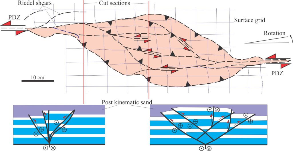
Layering depicted in the two cross-sections has been simplified from the published examples. The faults form a characteristic positive flower structure close to the left PDZ and are more fan-shaped in the antiform popup centre. Both diagrams redrawn from McClay and Bonora, 2001 op cit., Figures 3e and 4.
- Strike-slip displacement at restraining bends results in shortening, uplift, and oblique slip, reverse fault arrays.
- Pop-ups have broad antiformal geometry. In map view they are sigmoidal to rhomb-shape.
- Riedel shears formed early in the deformation, linked to the PDZ at both ends of the pop-up.
- The pop-up structure is bound by two oblique slip reverse faults having sinistral displacement – the same as the main PDZ. They are the primary detachments for the pop-up, linking with the PDZ. Strain is also partitioned along several smaller, internal faults that have similar displacement vectors and are mechanically linked to these detachments.
- Fault arrays near the transition with the PDZs have characteristic positive flower structures (and contrast with the releasing bend models). The arrays are more fan-shaped in the centre of the pop-ups.
- The central part of the model rotated 6° counterclockwise.
Releasing bend step-over model
This set of experiments examined basin pull apart and faulting under pure and oblique extension (transtension) across a releasing bend stepover (Wu et al., 2009, op cit.).
In real pull-apart systems, strain is distributed through the crust and within the basin fill during fault displacement and basin subsidence. This is manifested as progressive shingling of sedimentary packages (see the original description of this process by Crowell, 1974, op cit.), and by folds and faults within the stratigraphic fill and basin margins (e.g., flower structures). These conditions are duplicated in the model using a thin rubber sheet beneath the plate boundary (to maintain extensional stress), and placement of a thin sheet of silicone polymer above the base plates to represent ductile lower crust. To generate oblique-slip in this model, the boundary between fixed and mobile base plates must also be oblique – i.e., at an angle to the extension direction induced by the motors. This configuration is shown in the diagram above (only the transtension model is shown here).

Summarizing the results:
- The transtensional basins were wider than those developed during pure strike-slip.
- Transtensional basin margins were cut by en echelon extensional faults.
- The faults are either oblique slip or dip slip (cf. the predominance of reverse faults in the transpressional model).
- Pure strike-slip pull-parts had a single depocenter, but the transtensional basins had two opposing depocenters.
- Cross-basin strike-slip faults in the transtensional models separate the two depocenters.
- In both sets of experiments, the first manifestations of deformation are Riedel shears above the PDZ, and with continued extension, these formed en echelon arrays that linked the PDZ step-over.
- Oblique dip-slip basin wall faults continued to grow during extension– these formed the boundaries of basins in both the pure and oblique strike-slip experiments.
- Sidewall faults in pure strike-slip models are a single strand; in the transtensional models they are segmented, consisting of low angle, en echelon arrays.
- All major oblique dip-slip faults were mechanically linked to the primary PDZ.
- In both the pure strike-slip and transtension model sets, the fault arrays formed negative flower structures – relatively simple in the pure strike-slip experiments, but more complex in the transtensional models.
- Faults above the PDZs were close to vertical; those above the stepover were slightly shallower.
- The overall configuration of displaced strata in 2D cross-sections is synformal (opposite that in the transpressional model).
Comparisons with modern basins
Overall, the modeled structural configurations at restraining and releasing strike-slip fault stepovers are remarkably similar to modern real-world systems. The comparison applies to basin shape and the mechanics of the fault arrays. Incorporation of synkinematic deposition in the releasing bend pull-apart models successfully reproduces the stratigraphic relationships with active faulting at the basin margins and within the basin fill.
Restraining bend popups tend to be rhomb-shaped and bound by oblique slip reverse faults that tend to flatten upwards into positive flower structures. Faulting produces broad antiforms that in some examples are doubly plunging (towards each PDZ). Larger, through-going faults are mechanically and kinematically linked to the PDZs. Real world popup structures will be subject to erosion – this was not incorporated into the models.
McClay and Bonora (2001, op cit.) cite examples of restraining bend and thrust faulted popup structures along the San Andreas fault system and Atacama Fault System (northern Chile), where there are reasonable comparisons between modeled and real flower or palm tree fault arrays and antiformal stratal geometry.
Releasing bend pull-apart basin models also show good comparison between basin configuration and fault geometries with real world examples. The Gulf of Elat basin is located on the same transform as Dead Sea but displacement vectors change from one basin to the other – relatively pure strike-slip associated with Dead Sea, and sinistral displacement having 5o obliquity to the strike of the Elat basin. Like the modeled examples, the Gulf of Elat basin sidewall faults are partitioned into en echelon fault arrays. The Gulf example also has 4 main depocentres where the basin is partitioned by internal dip-slip faults.
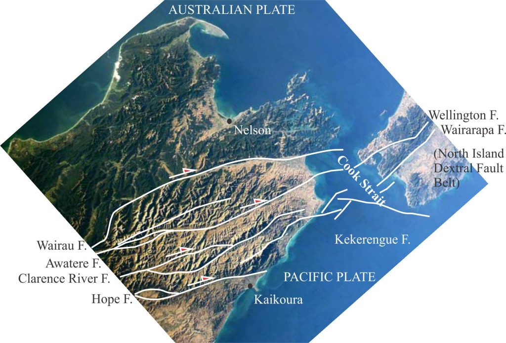
The comparisons between pure and oblique strike-slip basins also appears to be compatible with the Marlborough Fault system in Aotearoa New Zealand, where strain on the Alpine transform is partitioned into several dextral strike-slip faults in the northern part of South Island. Here, examples of pure and oblique releasing bend basins occur and in general those undergoing oblique displacement are bound by arrays of overlapping faults, whereas basins associated with pure strike-slip are bound by single sidewall fault strands.
Model limitations
McClay and Bonora (2001, op cit.) note some of the limitations that model conditions impose on the resulting structures and basin form – most of these caveats apply to other analogue model types.
- No account is taken of thermal effects, that potentially have a strong influence on material viscosity and ductility.
- The isostatic effects of crustal loading and unloading are not incorporated into the models.
- Most models are one or two layers thick. This usually means that models are rheologically isotropic. However, real world rock sequences usually show much greater rheological variability which means significantly greater variability in styles of deformation than those witnessed in the models.
Other posts in the series on geological models
Geological models: An introduction
Model dimensions and dimensional analysis
Analogue models of faults: scaling the materials
