Stereographic plotting of linear structures and measurements.
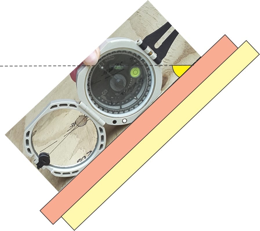
Geologists are interested in the orientations of rock and mineral structures. We spend a lot of time measuring the geometry and orientation of these structures, in the field and lab, with Brunton compass or down a microscope. We do this to determine the direction of movement, the orientation of stress fields, or the directions of paleocurrent flow. All these “directions” can be described by linear features – many are real structures such as sedimentary flute casts, or mullions. Others are imaginary, like fold axes. All can be represented stereographically. Some common linear features are listed below:
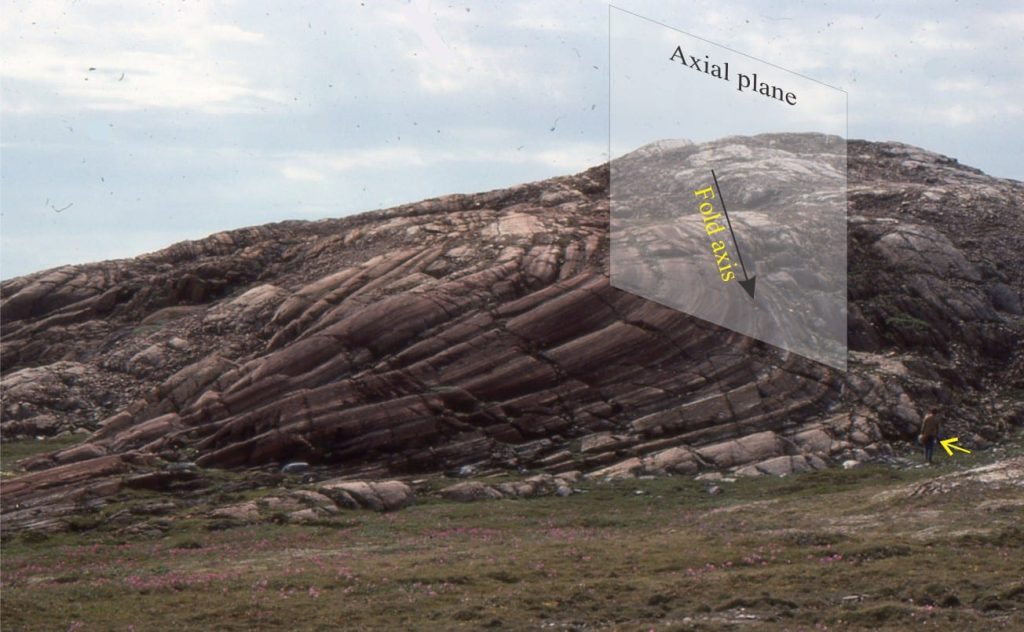
Axes: Fold axes, slump axes, crystallographic axes.
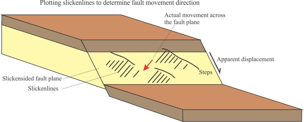
Structural lineations: mineral alignment, mullions, rodding and pencils, slickensides, fault-fracture-joint traces, cleavage-bedding intersections.
Sedimentary structures: flute and groove casts, clast and fossil alignment, parting lineation, paleocurrent flow directions.
Some general considerations:
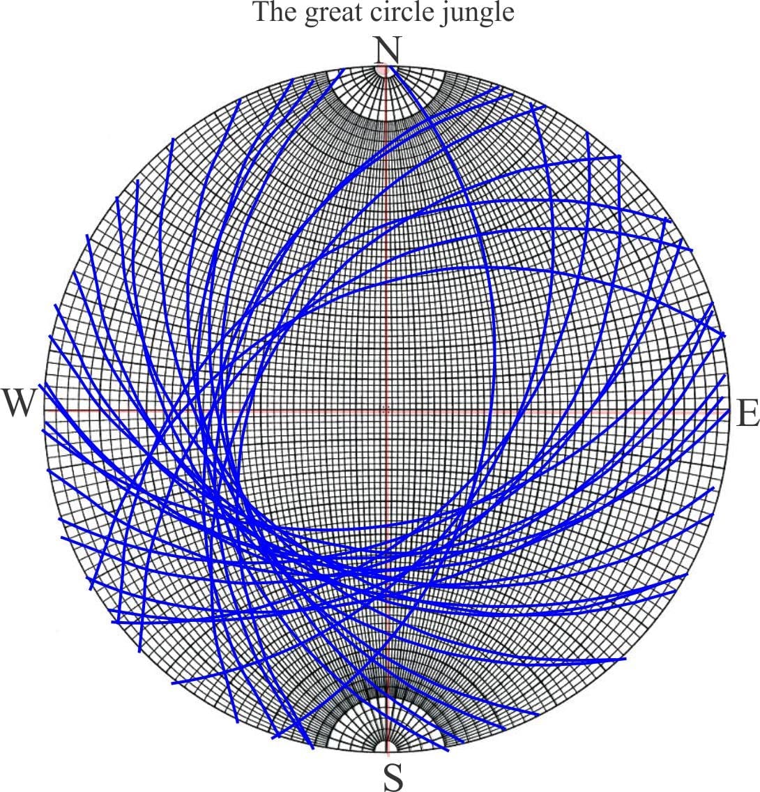
- Planes (dip and strike) plot as great circles on a stereonet.
- The stereonet perimeter represents zero dip, or horizontal; the centre is vertical dip (90o).
- Lineations, axes etc. will have an azimuth, and an angular relationship to the strike of the plane, whether that angle is measured in the plane (e.g. rake), or from the horizontal (plunge).
- Any lineation will plot as a point on the great circle representing planes such as bedding, foliation, fault, axial surface.
- Any great circle is intersected by small circles.
Great circles are used to determine the orientation of planes. Small circles are used to measure angular relationships between linear features and that plane; this includes the line of intersection between two planes. All angular values are counted along small circles from either the N or S marker (pole) on the stereonet, depending on the azimuth or bearing of the linear element. For example, an azimuth of 110o (ESE) will be plotted from the South marker; an azimuth of 290o (WNW) from the North marker.
The difference between dip, plunge, and rake
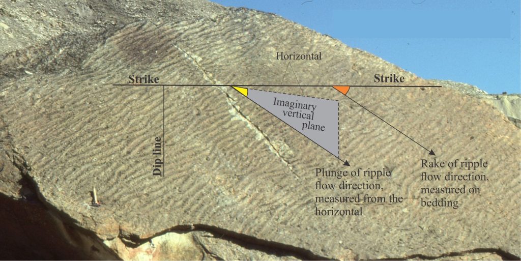
In geology, we measure the orientation of linear features relative to the plane in which they occur – an axial surface, bedding, or fault plane. Any inclined plane contains imaginary horizontal lines (strike), and a dip line on the plane and at right angles to strike that represents the maximum inclination with respect to a horizontal datum. The orientation of any plane is defined uniquely by its strike and dip.
The orientation of a linear feature on the plane can be measured with reference to the strike of the plane, and any (imaginary) horizontal line or plane that intersects the strike. Any linear feature can be described by its plunge, or its rake (pitch).
The plunge angle of a linear feature is its inclination relative to a horizontal line/plane; it is analogous to dip but has smaller values of inclination. The plunge line will also have a unique bearing – for example, a fold axis plunging 30o SW.
The angle of rake of the same linear feature is measured from the strike IN THE SAME PLANE. The rake line also has a bearing.
NB: It is imperative that both angle and bearing are recorded for plunge and rake (and dip).
An example
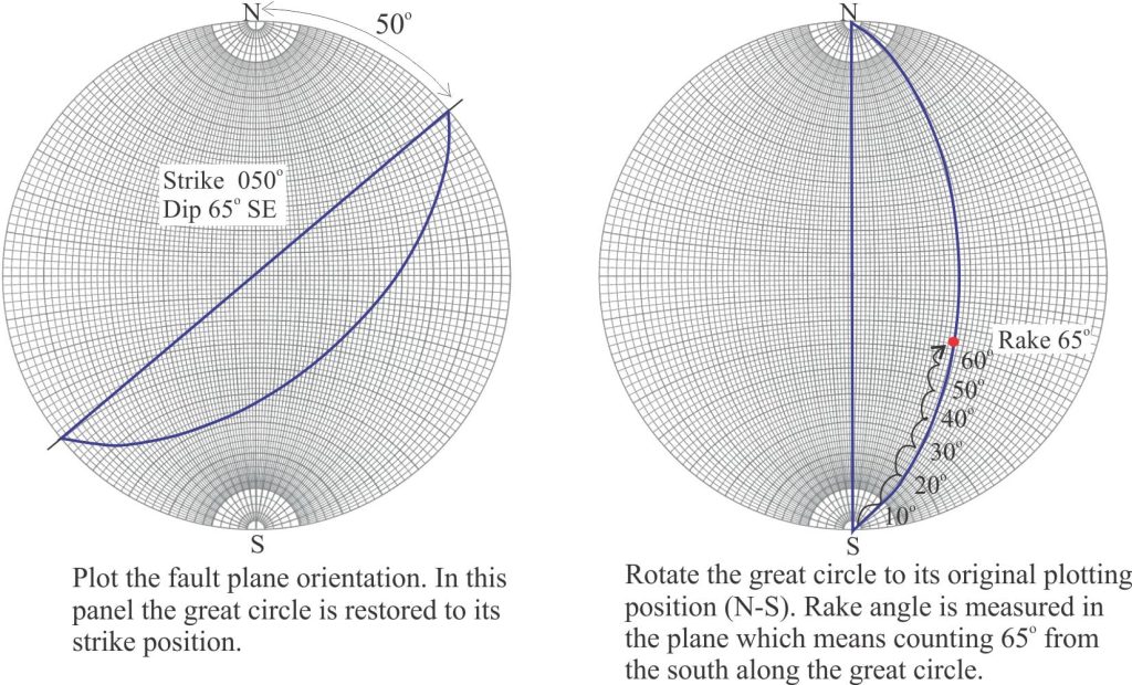
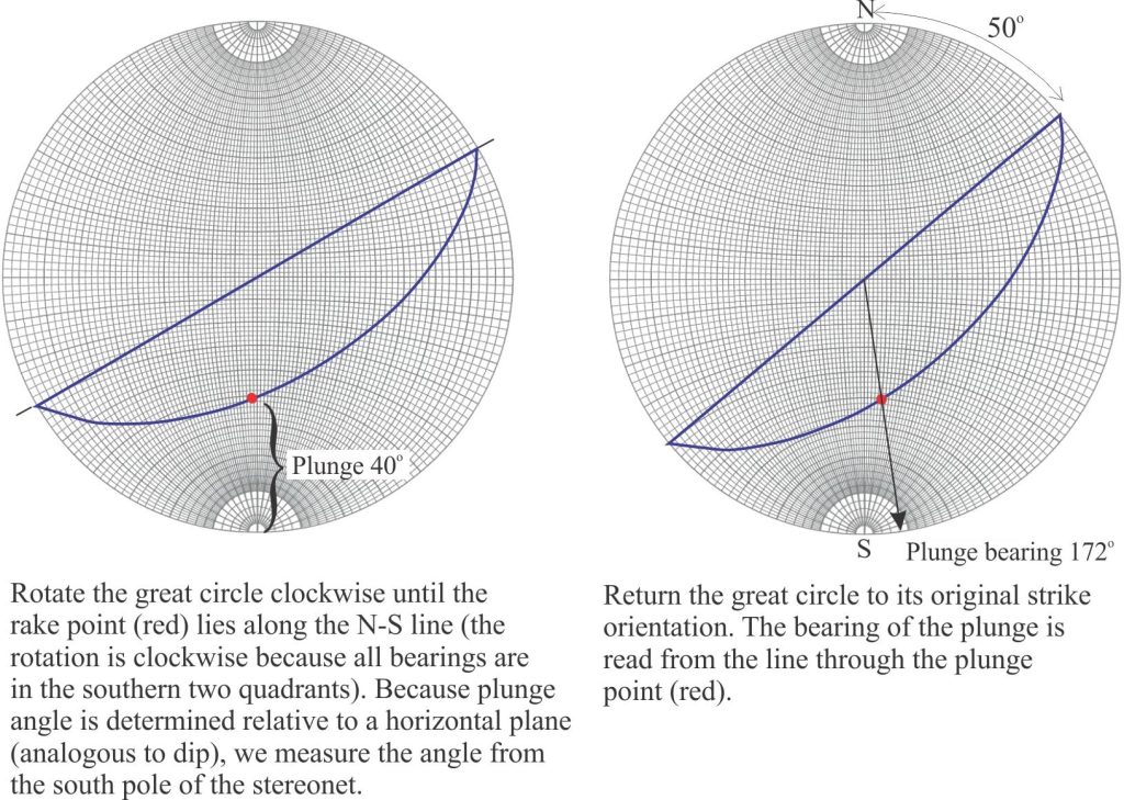
Here is an example: Slickenlines on a fault plane striking 040o (N40o E) and dipping 50o SE, have a rake of 65o SW. Using a stereonet, find the plunge and plunge azimuth (bearing) of the slickenlines.
Here is a guide to plotting planes on a Wulff stereonet.
Some other posts in this series:
Stereographic projection – the basics
