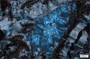
Petrographic (optical, polarizing) microscopes open doors to the architecture of rocks – crystals, grains, cements – a riot of colour and texture. Here is some common terminology that students will encounter on their journey through the lens. The entries have a semblance of order, beginning with the structure and symmetry of crystals, segueing through the important optical properties that form the basis for mineral identification.
My own experience at undergraduate level with the theory behind optical mineralogy was a bit chequered. Looking down the microscope was exhilarating, but marrying the kaleidoscope of shape and colour with the theory wasn’t as simple as my tutor made it out to be. So, for anyone beginning their foray into this subject, I hope the notes below help. Optical mineralogy is key to understanding the mineralogical and chemical evolution of rocks, their compositional and textural changes, their paragenesis. So persevere!
The terminology
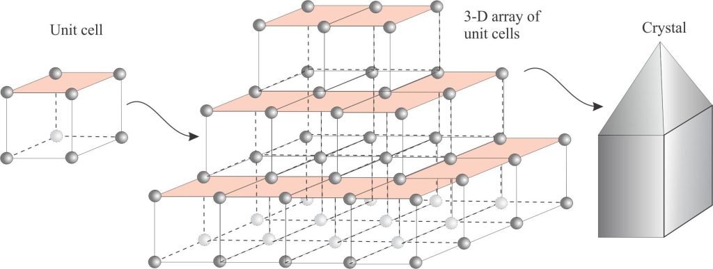
Unit cell: At the atomic scale, the arrangement of atoms that represents the fundamental structure of a mineral in crystal form. The crystals we see consist of a three-dimensional array of stacked unit cells. This means that the overall shape of the crystal mimics its unit cell. The simplest unit cell is a cube; cubes of the same size will stack perfectly. Not all polygonal geometries allow such stacking, for example cells with triangular sides will stack neatly together, but those with 5-sided faces (pentagons) will not. Consideration of the unit cells and their symmetry form the basis for definition of the 6 (or 7) crystal systems.
Crystallographic axes: Three or four axes about which a crystal can be rotated through 360o. The axes intersect at a single point (the centre of symmetry). They are labelled according to their lengths. If axes are the same length, then they are referred to as a1, a2, a3 etc. If they have different lengths, they are labelled a, b, and c. Thus, in the cubic (isometric) crystal system they are labelled a1, a2, a3, and in the tetragonal system a1, a2, c. The hexagonal system is the only one with four axes. Angles between axes are labelled α, β, γ.

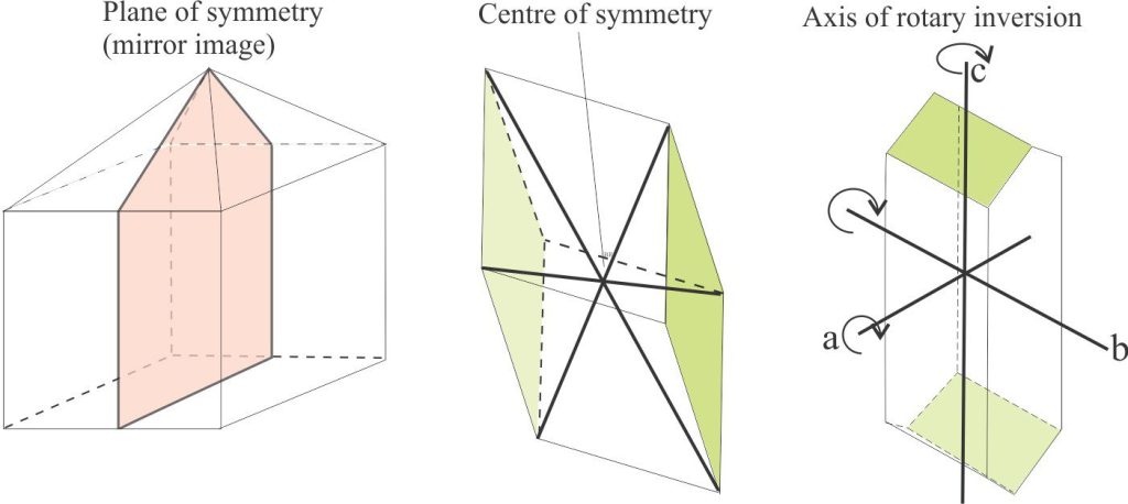
Crystal symmetry: Symmetry describes the shape of an object and can be represented both mathematically and visually. In crystallography, the two most useful forms of symmetry are (mainly because they are the easiest to visualize):
- Axes of rotation (crystallographic axes) where a particular crystal face will be repeated during rotation through 360o. The number of repetitions for a 360o rotation can be 2, 3, 4, or 6, that are referred to as two-fold, three-fold, four-fold, and six-fold (axial) symmetry respectively.
- Planes of symmetry where two parts of a crystal are mirror images. For an analogy, think of this concept in terms of the common bilateral symmetry in many living organisms, such as people, and many classes of mollusc. Note that planes of symmetry are NOT the same as twin planes.
- Additional elements of symmetry include: A centre of symmetry, where a crystal face is reflected from one side to another or is repeated by inversion, and an axis of rotary inversion.
Crystal systems: There are 6 crystal systems based on combination of the elements of symmetry; a seventh system – trigonal – is sometimes considered a subclass of the hexagonal system. There are 32 crystal classes based on combinations of the symmetry elements. The defining criteria are axial lengths, the angles between axes, and axial symmetry (the number of repetitions about an axis).
- Cubic (or Isometric) system: The most symmetric group. All three axes are the same length and are at right angles to each other.
a1 = a2 = a3 α = β = γ = 90o
2, 3, and 4-fold symmetry depending on the class
Common crystal forms: cubes, octahedra, dodecahedra: e.g., Halite, pyrite, fluorite, garnet
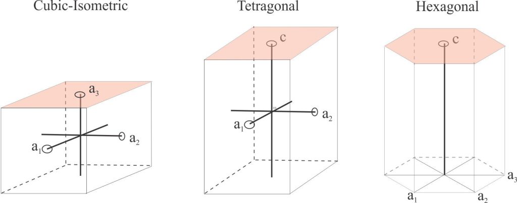
- Tetragonal system: Liken this group to isometric crystals stretched along the c
a1 = a2 ≠ c α = β = γ = 90o Mostly 2- and 4-fold symmetry
Common crystal forms: Prisms, bipyramids with or without prisms: e.g., zircon, chalcopyrite, rutile
- Hexagonal system: This system has 4 axes, 3 of which are perpendicular to c
a1 = a2 = a3 ≠ c Angles between a1 = a2 = a3 = 120o
6-fold symmetry
Common crystal forms: Prisms, bipyramids: e.g., apatite, beryl,
The Trigonal subsystem has one 3-fold axis or rotation. Three important examples are quartz, calcite and dolomite, commonly formed as bipyramids, rhombohedra, and scalenohedra.
- Orthorhombic system:
a ≠ b ≠ c α = β = γ = 90o
2-fold symmetry
Common crystal forms: Prisms, bipyramids: e.g., olivine, cordierite, hypersthene
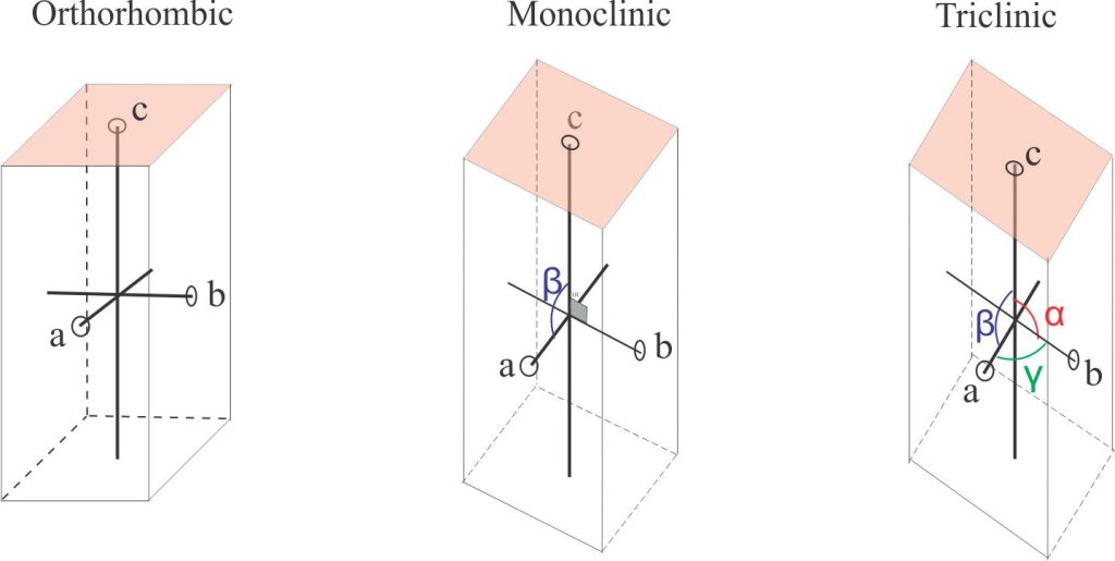
- Monoclinic system:
a ≠ b ≠ c α = γ = 90o, β ≠ 90o
2-fold symmetry
Common crystal forms: Prisms, pinacoids (flattened prisms): e.g., orthoclase, diopside, sphene, staurolite, most amphiboles.
- Triclinic system: The least symmetric group
a ≠ b ≠ c α ≠ β ≠ γ ≠ 90o
No axes of symmetry!
Common crystal forms: Prisms, bipyramids: e.g., microcline, plagioclase, kyanite
Plain polarized light: (PPL) The light transmitted through a polarizer, located below the microscope condenser (the condenser focuses this light through an opening in the rotary stage). The polarizer filters out all light frequencies other than those that vibrate in a single plane. The polarizers here are oriented E-W (Note the upper polarizer is oriented N-S). Minerals in thin section examined under PPL show important identifying characteristics such as crystal shape, cleavage, breakage patterns, relief, and pleochroism. The light path for PPL is shown diagrammatically below.
Crossed nicols (polars): The upper polarizer, between the objective lenses and the Bertrand lens, filters out all remaining frequencies present in plain polarized light (PPL). The nicols can be moved in and out of the light path. If you look through the oculars when the polarizer is in the light path (i.e., crossed nicols) then no light will reach the oculars – all will be black. However, if a thin section is placed between the lower and upper polarizers, most minerals will reorient the PPL such that some of this light will pass through the upper polarizer; this light will contain slow (ordinary) and fast (extraordinary) vibration directions that will arrive at the eye pieces at slightly different times. The resulting interference produces the kaleidoscope of colour among all the minerals present. Minerals that permit the passage of light are called anisotropic; those that do not are isotropic.

Extinction: As the microscope stage is rotated, under crossed nicols, either the fast or slow vibration direction of light exiting an anisotropic mineral will be blocked by the upper polarizer – at this point no light is transmitted through polarizer and it appears black – the transmitted light has been extinguished. This alignment occurs four times during one 360o rotation (because the fast and slow rays are perpendicular), and therefore each extinction event is 90o apart.
Extinction angle: The angle at which extinction occurs relative to crystal habit or prominent cleavage, may vary between 0o and 89o. The angle can be easily measured using the grid on the rotating stage. Extinction angles can be used to help identify minerals.
- Parallel extinction: Extinction parallel to the crystal elongation direction or cleavage, that also parallels the crystallographic c axis. A common example is muscovite
- Inclined extinction: The most common type, between 0o and 89o.
- Symmetrical extinction: In minerals that have two prominent cleavage planes (such as calcite) – if the extinction angles measured from each cleavage are the same, then extinction is symmetrical.
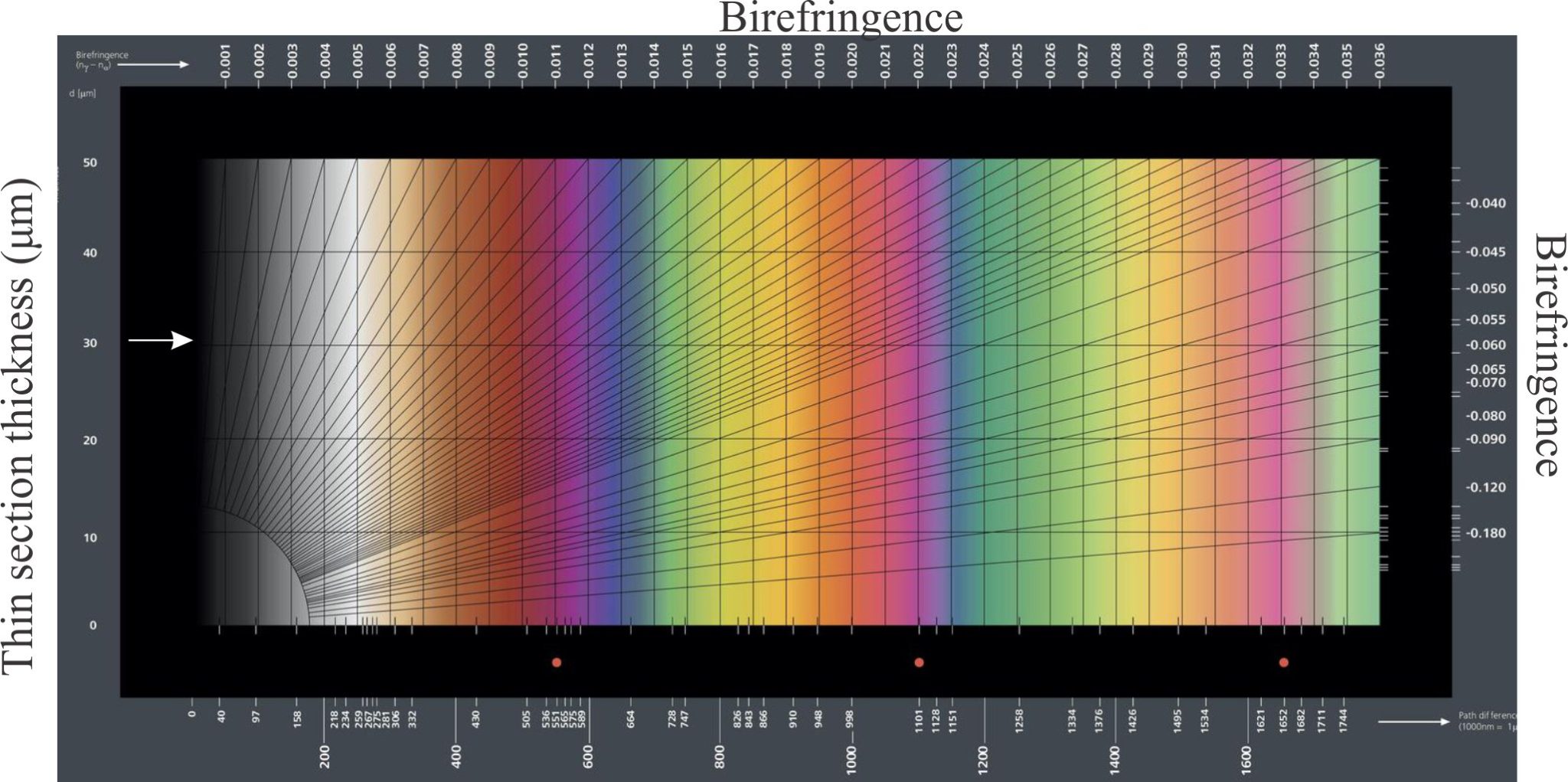
Birefringence: Plain polarized light that passes through a mineral is resolved into mutually perpendicular fast and slow rays that will each have different indices of refraction as (i.e., their refraction paths and velocities will be different). Birefringence is the maximum difference between these two index values. Under crossed nicols, the difference is manifested in the ‘intensity’ of interference colours. For example, quartz has low birefringence showing typically as first-order greys, whereas high birefringent calcite displays 3rd-order colours. A typical chart showing the range of birefringence values and colours is shown below.
Isotropic minerals: Unlike anisotropic minerals, this group cannot reorient plain polarized light which means that no light will pass through the upper polarizer; they will appear black through all rotations of the stage. All isometric minerals (cubic system) are isotropic (e.g., garnet, fluorite, halite, spinels). Note that an anisotropic mineral oriented at right angles to its optic axis will appear isotropic (because there is no resolution of fast and slow rays along the optic axis, i.e., no birefringence).
Anisotropic minerals: Minerals in thin section reorient plain polarized light, resolving it into two vibration directions that will pass through the upper polarizer when nicols are crossed. One direction contains a fast light ray (also called the extraordinary ray), the other a slow ray (ordinary ray); the fast and slow rays are perpendicular to each other. In thin section minerals appear coloured and will go into extinction four times during a 360o rotation of the stage (and thin section). Anisotropic minerals are further divided into uniaxial and biaxial based on the presence of one or two optic axes.
Optic axes: Axes along which plain polarized light is NOT split into fast and slow rays. In other words, there is NO birefringence parallel to an optic axis. Minerals having a single optic axis are uniaxial; those having two are biaxial.
Interference figures: These appear as curved isogyres or crosses when a mineral is viewed under crossed nicols at high magnification with the Bertrand lens inserted. There are two basic types:
- Uniaxial crosses that do not break up or rotate as the stage is rotated.
- Biaxial isogyres or crosses that rotate and move with the stage; crosses will break into two curved isogyres.
Determining the +ve or -ve signs for either case is described under the Uniaxial and Biaxial headings.
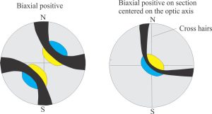
Biaxial minerals: Anisotropic minerals where plain polarized light entering at any angle, other than along two optic axes, is resolved into two planes of polarized light; these two planes each contain the fast and slow rays. The resulting colour depends on the different in the refractive indices of these two light paths – i.e., the birefringence. Note that mineral sections perpendicular to the optic axes will appear isotropic. Some typical interference figures are shown below.

Minerals may be positively or negatively biaxial, depending on the orientation of fast and slow rays. Determining the sign (+ve or -ve) is done as follows:
- Zoom in on the mineral of choice to the highest possible magnification (under crossed nicols).
- Insert the Bertrand lens. You will (hopefully) see interference figures manifested as curved isogyres or isogyre crosses.
- Rotate the stage and observe how the isogyres rotate; a cross will break up into separate isogyres.
- Orient an isogyre until it is concave to the NE.
- Insert the accessory plate (a plate containing a gypsum wafer) and note the change in colour on the immediate inside of the isogyre, from first-order grey to:
- 1st-order blue, if the mineral is biaxial +ve
- 1st-order yellow, if it is biaxial -ve.
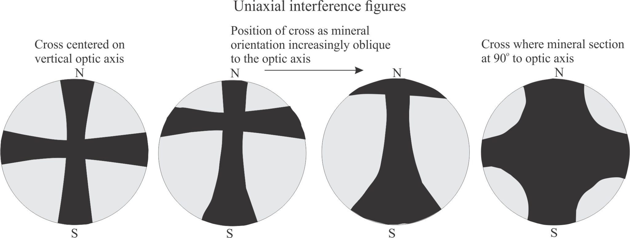
Uniaxial: Anisotropic minerals where plain polarized light entering at any angle other than along a single optic axis, is resolved into two planes of polarized light; these two planes contain the fast and slow rays. The resulting colour depends on the different in the refractive indices of these two light paths – i.e., the birefringence. Note that mineral sections where the optic axis is vertical will appear isotropic under crossed polars. However, when the Bertrand lens is inserted, you will see a dark cross that is also centered.
Note too that the N-S axis of the interference cross parallels the fast (extraordinary) ray, and the E-W axis the slow (ordinary) ray.
Minerals may be positively or negatively uniaxial, depending on the orientation of fast and slow rays. Determining the sign (+ve or -ve) is done in the same way as biaxial minerals, except:
- The interference figure is a cross that DOES NOT split into curved isogyres when the stage is rotated. Nor does the cross rotate. If the mineral is oriented such that the optic axis is vertical, then the cross will not move across the field of view as the stage is rotated. Mineral sections oblique to the optic axis will show variable positions of the cross, but will remain oriented N-S/E-W.
- When the gypsum plate is inserted the colour in the NE quadrant will become blue if uniaxial +ve, and yellow if uniaxial -ve. The most common uniaxial +ve mineral is quartz.
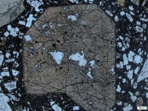
Relief: Light is refracted, or ‘bent’ when it passes from one transparent material to another (air to water; air to thin section mineral); refraction corresponds to a change in direction and either an increase or decrease in velocity. The refractive index (RI) of a mineral is the ratio of the velocity of light in air to that in the mineral. Indices differ amongst minerals such that:
- Isotropic minerals have a single RI
- Uniaxial minerals have two RI along different axes, and
- Biaxial minerals have 3 RI.
The different RIs for any mineral are manifested as relief in plain polarized light, where one mineral may appear to stand above or below its neighbours. The orientation of uniaxial and biaxial minerals will also determine their relief. This is a useful criterion for mineral identification. For example, most ferromagnesian minerals have relatively high relief compared to quartz and feldspar; calcite and dolomite relief is even greater. However, quartz and feldspar have very similar relief and the distinction, particularly for untwinned potassium feldspars, must rely on criteria such as cleavage and interference figures.
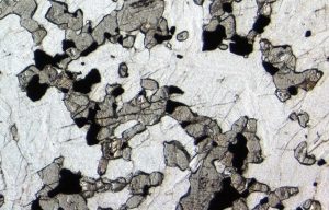
Pleochroism: In plain polarized light, some minerals change colour during rotation of the stage. Colour changes may be subtle or intense. Pleochroism is a useful criterion for mineral identification. Common examples in sedimentary rocks are:
- Amphiboles in various shades of green and yellow – hornblende has fairly intense pleochroism in shades of olive green, glaucophane in shades of blue and blue-green.
- Pyroxenes in various shades of green and brown.
- Micas – muscovite is usually colourless but may be pleochroic in pale reds or browns, Biotite is strongly pleochroic in shades of brown, as seen in the video below. In this example the biotite is from a well foliated greenschist (Otago Schist, New Zealand); the view is under plain polarized light. A small, partly rotated garnet has nudged next to the biotite blades.
Cleavage: A plane of weakness within a crystal that will break with relative ease. It is caused by weak bonds between planes of atoms within a crystal lattice; the pattern of weakness repeats regularly through a crystal. Some minerals have poor or no cleavage (e.g., quartz, olivine); others have excellent cleavage along several lattice planes (e.g., calcite, feldspar). Cleavage is a defining characteristic of a mineral, particularly in thin section.
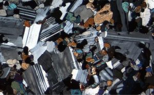
Twinning: A symmetrical intergrowth of two separate crystals of the same mineral, that share the same mineral lattice. In thin section under crossed nicols, each twin segment will go into extinction at different rotations of the microscope stage. There are many kinds of twinning. For example, plagioclase may show albite, carlsbad, or pericline twins individually or as combinations in the same crystal. Important optical properties of twins that help mineral identification include extinction angle (whether straight or inclined), and 2V angles. Note that twin planes are NOT the same as planes of crystal symmetry.
Crystal zoning: Zoning commonly displays as concentrically arranged crystal growths, where the composition changes outwards from the crystal interior. The zones maintain the same crystallographic and optic axes. The changes in composition involve substitution of certain cations. For example, in calcite, Fe2+ and Mn2+ substitute for Ca2+, and in plagioclase sodium may substitute for calcium such that the inner core of a crystal is a calcium anorthite and the outer zone is a sodium albite. Zoning indicates changing fluid or magma crystallization conditions. Zoned crystals may also be twinned.
Here are some excellent sites and texts that provide greater detail
Raith, M.M., Raase, P., and Reinhardt, Jurgen. (2011) Guide to Thin Section Microscopy. Open access PDF
Johnson, E.A., Liu, J. C., and Peale, M. Introduction to Petrology. Licensed under CC-BY-SA 4.0. Source
Heinrich, E.WM. 1965. Microscopic identification of minerals. McGraw Hill. An old text but still gold.
Other posts in this series
Miller Indices in crystallography
Lithic grains in thin section – avoiding ambiguity
Ignimbrites in outcrop and thin section
The mineralogy of sandstones: porosity and permeability
The mineralogy of sandstones: Quartz grains
The mineralogy of sandstones: Feldspar grains
The mineralogy of sandstones: lithic fragments
The mineralogy of sandstones: matrix and cement
