This is the first post in a series on the geological world under a microscope
As a kid visiting my Scottish grandparents, I would make a bee-line for two delights in their house (after the hugs); the kitchen (following my nose) to the inevitable trays of homemade donuts and shortbread, and the living room credenza wherein was kept an old kaleidoscope. It was a triangular prism (most modern forms are tubes), filled with glitter, two mirrors at one end, and a peep-hole at the other. This simple toy introduced me to the world of symmetrical, kaleidoscopic, never-repeated patterns. Years later, as a geology student, I was introduced to optical mineralogy, the science and art of identifying minerals under a polarizing microscope – flashbacks to my childhood.
All rocks are composed of minerals, as crystals or grains. Knowing which minerals make up a lava flow or a sandstone helps geologists decipher something of the rock’s history; where it came from, how it formed, and what might have changed within the rock and its minerals since they came to be. Chemical analyses will tell us which elements are present (iron, magnesium, silicon and so on), methods that utilise X-rays or electron beams will provide details of the internal organisation of minerals, but if we want a visual image of the inside of rocks and minerals, then microscopes, that have been around since Galileo’s time, are still the best tools for the job.
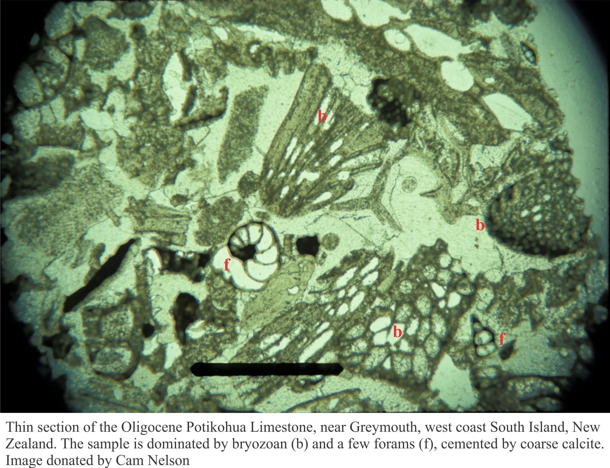
Most rocks tend to be dense and thoroughly opaque. To overcome this technical hitch we must slice our samples very thinly. A small slab of rock (few millimetres thick) is glued to a clear glass slide (standard size is about 26 x 46 mm). The rock is then ground to a thickness of 30 microns (30 millionths of a metre, or 0.03 mm); at this thickness, most rock components will transmit light. Samples prepared in this way are called thin-sections.
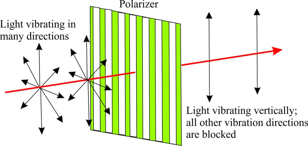
An optical microscope looks pretty much like any other mono- or binocular microscope, with one important difference; the light that is directed through the rock thin-section to the eye-piece is polarized. Normal white light contains waves (frequencies) that vibrate in different directions. The diagram shows a polarizer that allows only light vibrating vertically to pass through – all other vibration directions are blocked. The light that is transmitted through the polarizer is referred to as Plane Polarized Light (because it vibrates in only one plane).
Think polarizing sunglasses! Your glasses have a coating that removes the horizontally vibrating light (such as reflected glare). Hold your polarizing sunglasses towards the sky (not directly at the sun!) and rotate them 90o. The image will change from dark to light because horizontally vibrating frequencies (glare) can now pass through. This basic principle also applies to polarizing microscopes.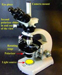 For a typical microscope, white light is polarized to a single plane; the plane polarized light passes through the thin-section and into the eye-piece. Thin-sections are placed on a rotating platform, or stage; rotation changes the orientation of minerals in the thin-section with respect to the plane polarized light, a process that can produce subtle changes in a minerals appearance.
Examining minerals in plane polarized light is usually the first stage of an investigation, wherein we look at basic properties such as crystal or grain shape, colour, and the geometry of internal structures like microfractures, or cleavage (cleavage reflects the ease with which a mineral will split, or cleave along a preferred plane).
However, a polarizing microscope’s analytical capabilities are significantly enhanced with the addition of a second polarizer, this one placed between the thin-section and the eye-piece. The second polarizer, which can be moved in and out of the view, is oriented at right-angles to the one below the thin-section (and the stage); When the second polarizer is inserted, it crosses the polarizing direction of the lower polarizer; this is referred to crossed polars or crossed Nicols. This means that when the stage (and thin-section) is rotated, some of the minerals will go dark (because no light is being transmitted through them to the eye-piece), and others will become lighter (a bit like the sunglasses). Continue the rotation and the opposite occurs. A mineral that becomes dark as the stage is rotated is referred to as going into extinction (i.e. no light passes through the crystal because it has been blocked by the second polarizer). Crystals commonly display different characteristics when viewed under crossed polars, characteristics that provide valuable clues to deciphering rocks and the minerals themselves.
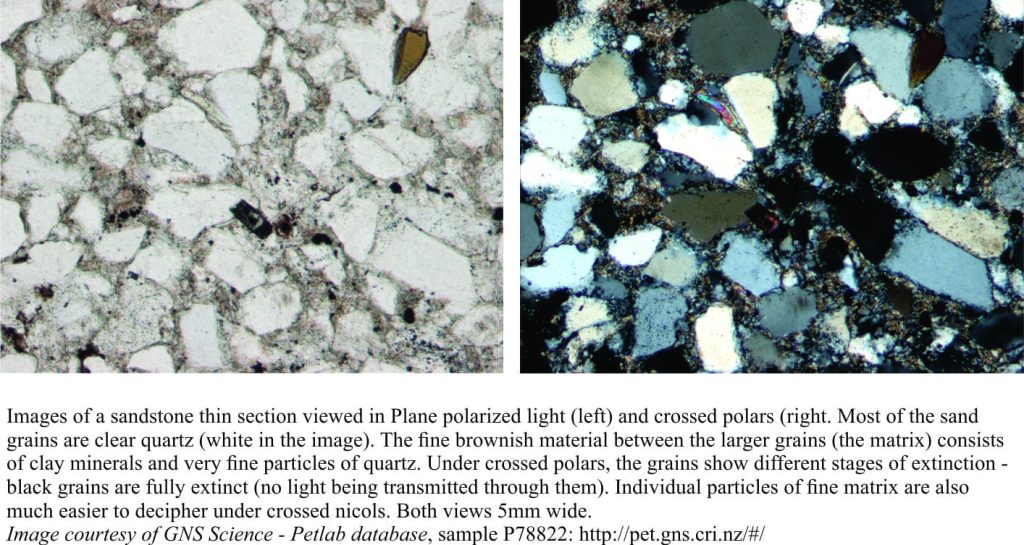
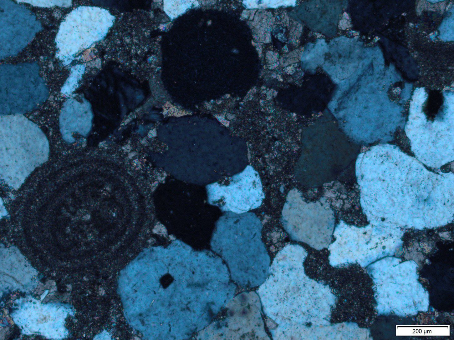
The difference between thin-section views in plane polarized light and crossed polars is quite stark, from both a visual and interpretive perspective. In the sandstone portraits below, we can visualize individual grain shapes (originally loose sand) in plane light, and see that internally most grains are featureless. Under crossed Nicols we see grains in different stages of extinction; in this example, the grey hues (in addition to other properties) are typical of the mineral quartz. Both views allow us to confidently announce that this particular sandstone sample consists mostly of quartz grains (we can say quite a bit more about this sample, but that story is for a future post).
Here are two brief videos of minerals responding to microscope stage rotation, under crossed polars. Both are examples of a rock type called gabbro, that formed as ancient magma cooled and solidified deep in the earth’s crust.
In the first video, several crystals of the common rock-forming mineral plagioclase (part of the feldspar group) pass in and out of extinction as the stage is rotated through 360o (the field of view is about 5mm). The second video shows different stages of extinction for feldspar (grey hues) and more brightly coloured olivine crystals (a silicate mineral with lots of iron and magnesium in its molecular structure); we can also see that these two minerals are intergrown.
The polarizing microscope brings to life the memory of a childhood toy. Any time I look at a rock thin-section through the eye-piece of a polarizing microscope, I am reminded of my grandparents’ credenza and the kaleidoscope; symmetry and colour, ephemeral images. As the microscope stage rotates, the changes in colour and hue reflect a world of symmetry in minute crystal microcosms. There is good science to be had with these microscopes, but there is also a reminder of how extraordinary the world is, at any scale.

