How to measure dip and strike
This post is part of the How To… series
If we had to designate one set of measurements that is fundamental to all geology, it would have to be Dip and Strike. These simple measures define uniquely the orientation (compass bearings and angles) of a planar surface – any plane: bedding, faults, axial planes, mineralized veins, dykes and sills. Armed with dips and strikes, a geologist can project planes and the rocks they encompass across valleys, through mountains and deep beneath the Earth’s surface. They are fundamental to deciphering Earth structures.
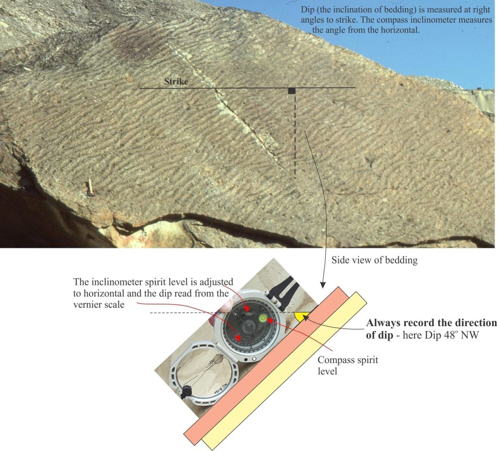
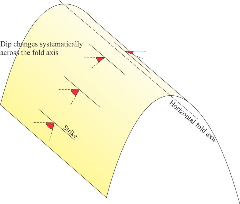
Strike: The compass bearing of an imagined horizontal line across a plane. If the plane is flat there is an infinite number of strike lines, all having the same dip (zero) but different bearings. If the plane is curved (e.g. a plunging fold) the bearing may change systematically over the fold.
Azimuth, or compass bearing is recorded as either (for example) 035o or N35E, or its counterpart 215o and S35W.
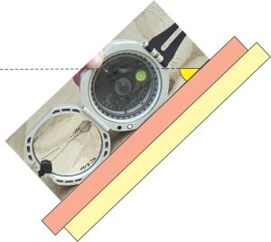
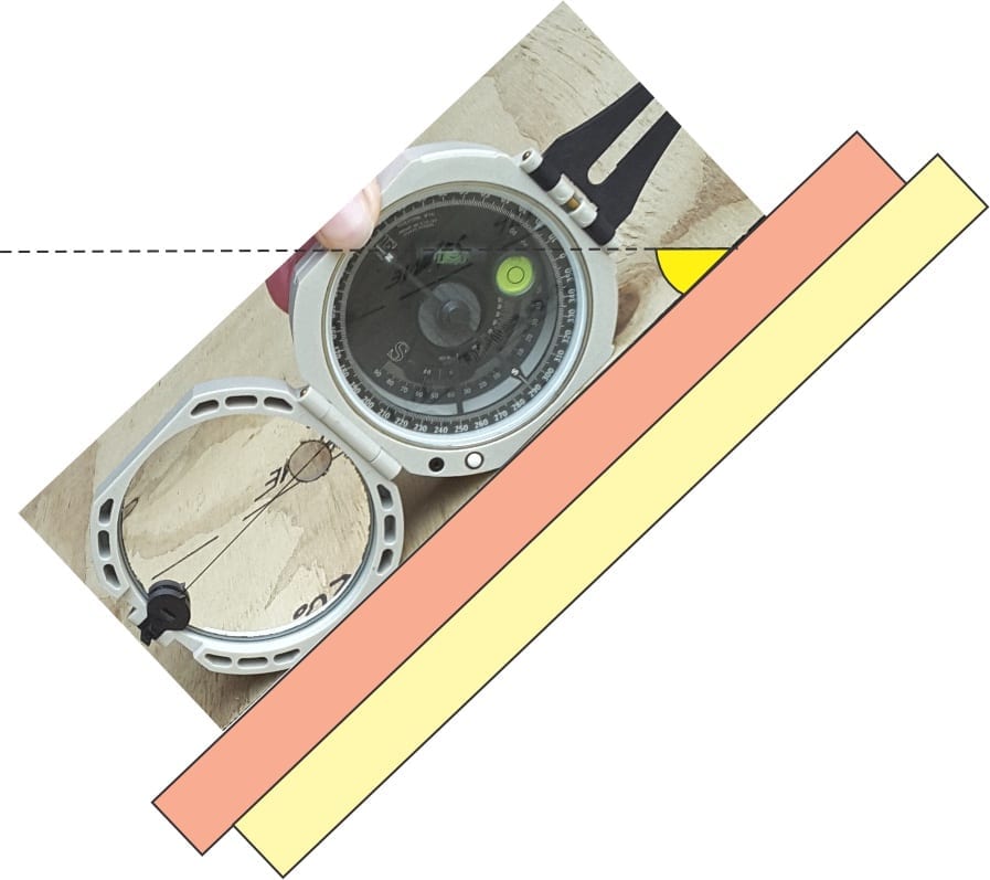
Dip: Dip is the angle of inclination measured from a horizontal line at right angles to strike. The angle is measured by placing a compass on the line of dip and rotating the inclinometer to the point where a spirit level indicates horizontal. The direction of dip need not be measured (it can be calculated directly from the strike bearing), but an approximate direction should always be recorded to avoid ambiguity, as in 48oNW.
The inclination measured at right angles to strike is the true dip. Inclinations measured at other angles on the plane will always be less than true dip – these are called apparent dips.
The animation below was made from still images: use the pause and play buttons as you work through the exercise.
Dip and strike indicate the orientation of a plane at a specific location. Dips and strikes of folded strata will tend to show systematic changes at different locations. In the example below the fold axis is horizontal and axial plane vertical. Strikes at any point on the fold limbs will all have the same azimuth, but dips will change progressively from one limb to the other. Dips and strikes recorded on geological maps can be used to reconstruct the 2- and 3-dimensional structure of deformed strata.
Some other useful posts in this series:
Solving the three-point problem
The Rule of Vs in geological mapping
Plotting a structural contour map
Stereographic projection – the basics
