The changing fortunes of fault permeability and fluid flow
Faults can act as conduits or barriers to fluid flow. As conduits they provide a focus for groundwater flow, geothermal activity, mineralization, and hydrocarbon migration. As barriers they impede both the vertical and lateral components of fluid flow and contribute to trapping of buoyant fluids like oil and gas.
Faults are the physical expression of localized strain. Faults, by definition, involve lateral displacement of rock bodies on either side of a fracture plane. Thus, the stress fields, whether extensional or compressional, inevitably involve components of shear (fracture networks that form by extension but lack lateral displacement are called joints). The initial permeability of a fault is influenced, first and foremost by the partitioning of dilational and shear strain that, in turn, determine the size or aperture of the conduit, and the degree of deformation beyond the principal fault plane. (A good summary has been compiled by Bense et al., 2013).
Fault rock description
There is a general expectation that faults will be encountered in almost any tectonic regime, whether extensional, contractional, or strike-slip. Faults are usually described in terms of their orientation and inclination, displacement vectors and stratigraphic offsets, structures on the fault plane (e.g., slickensides), and subsidiary structures such as drag folds. The basic descriptors in the context of fault permeability include (Caine et al., 1996, PDF available):
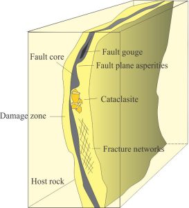
Fault core: This is the zone of greatest strain and displacement of hanging and foot walls in dip-slip faults, or lateral displacement in strike-slip faults. It is a zone of dilation that produces open conduits, and shear that rotates, translates, or breaks rock apart producing gouge and cataclasite. The core may consist of a single fault plane, or several closely spaced planes that are interconnected – the latter is called a distributed conduit. Interconnected faults are common in thrust fault splays, relay ramps, and flower structures.
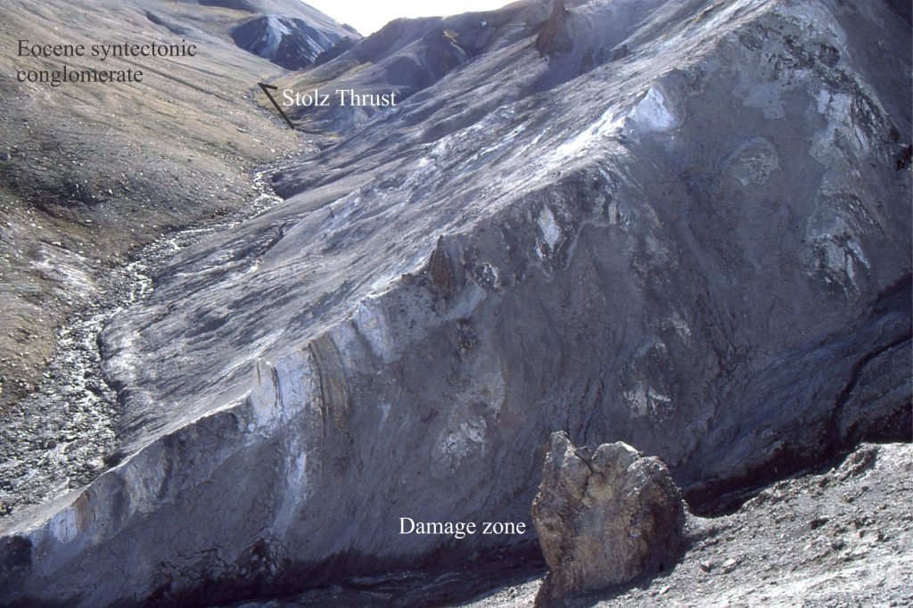
Damaged zone: This describes the zone of fracturing, crushing, grinding and grain diminution in fault blocks on either side of the core, the extent of which depends on the magnitude of the forces involved, the mechanical strength of the rock body, and how strain is partitioned. Brecciation is common. In general, the intensity of damage is a maximum closest to the fault core. Faults with large displacements also tend to have more extensive damaged zones. Damaged zones range in thickness (measured normal to fault planes) from a few millimetres to many 10s of metres.
The mechanical behaviour of rock
Faulting can occur in Earth materials that have a range of mechanical strengths, from weakly lithified sediment to strong, crystalline igneous rock. We can consider these two extremes as end members in terms of the partitioning of fault-plane strain (deformation), not only from one fault to another, but along each fault.
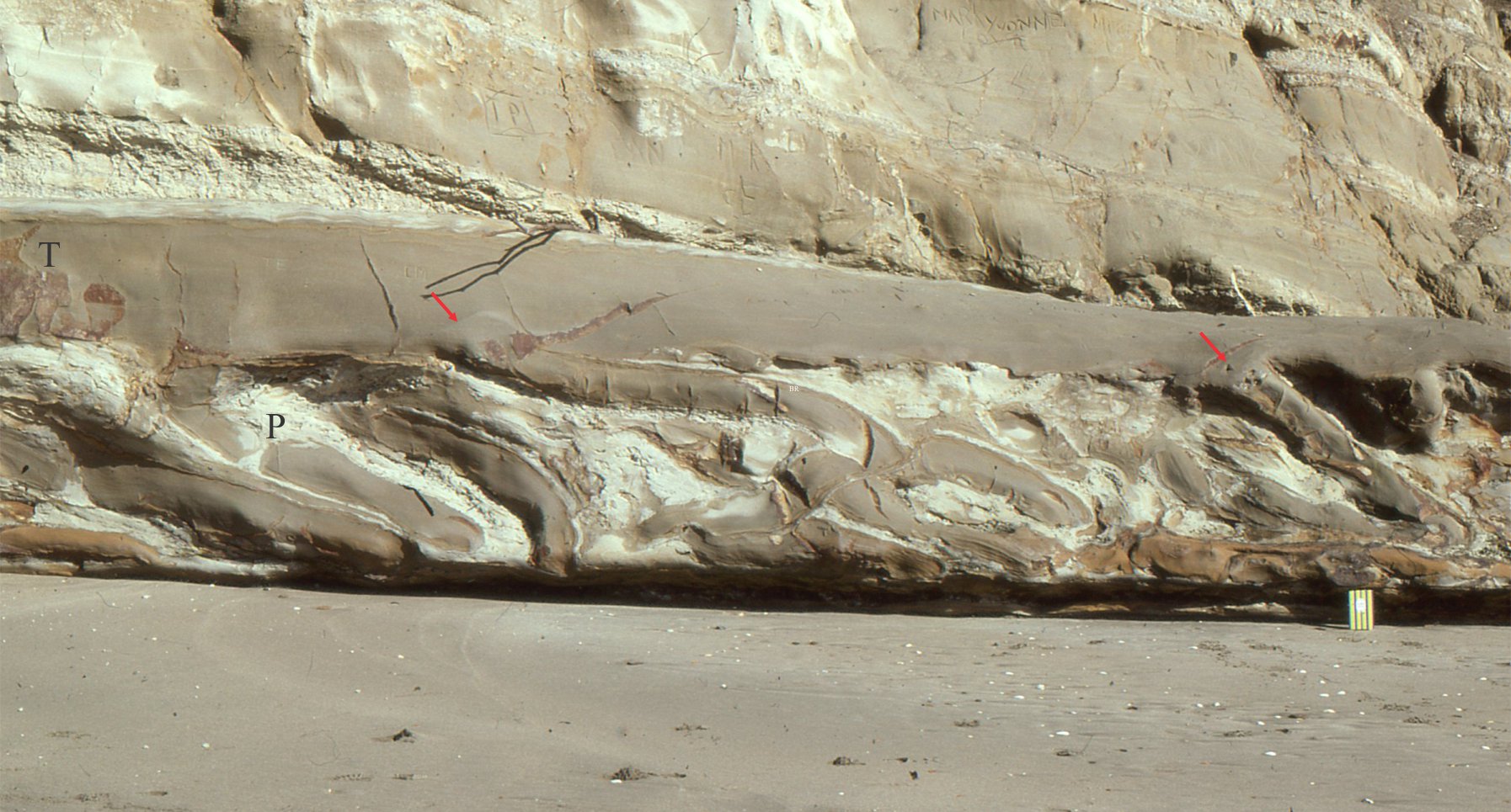
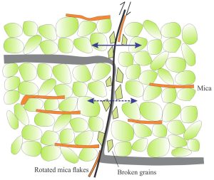
At one extreme, shear of nonlithified sediment is accompanied by grain rolling and sliding along the fault plane – this is known as particulate flow. In coarse-grained lithologies there is a rearrangement of the grain framework, and in some cases, breakage will reduce grain-size; minerals having good cleavage are prone to such breakage (e.g., feldspar). Muddy lithologies may be smeared along the fault plane and may even flow in situations where high fluid pore pressures develop. Mixing of different lithologies in the fault core is common in layered sedimentary successions.
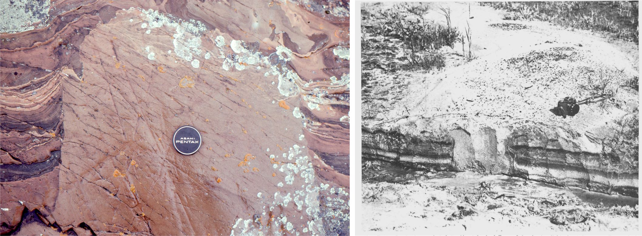
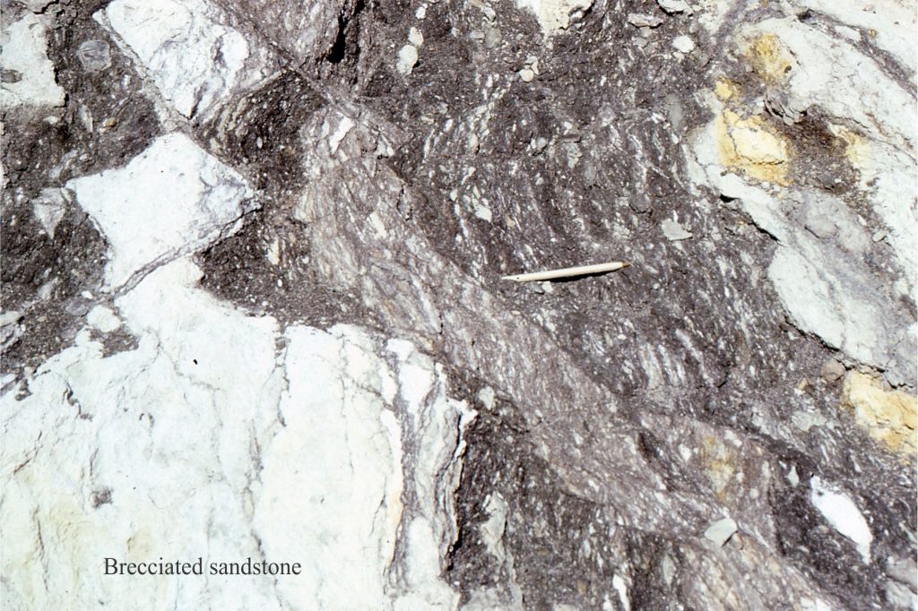
Faulting of hard rock produces a very different picture. Dilation can produce a network of fractures beyond the main zone of displacement. Components of shear will tend to rotate fracture blocks. Fault breccia will develop where shear is intense. Under more extreme conditions, shear can reduce rock to fine particles. The process of fault-zone crushing and fracturing of indurated rock is referred to generally as cataclasis. The degree of fracturing and brecciation in the damaged zone will decrease with increasing distance from the fault core. Weaker, fine-grained lithologies such as mudstone and shale, may be smeared along the fault core margins, and in some cases across the boundaries of individual fracture blocks in the damaged zone.
Initial fault permeability in weak rock
Particulate flow in weak rock involves grain rotation and sliding. In coarse-grained lithologies this process will alter the grain packing (compared with that in the host sediment) but the overall permeability may not change appreciably. However, in interbedded successions, there may be significant mixing of fine- and coarse-grained sediment, particularly if fault displacement is greater than bed thickness. In this case the permeability of material in the fault core will nearly always be less than that in the protolith (host rock/sediment). If there is extensive mixing of muddy sediment, the fault core may become a barrier to fluid flow.
In layered successions, the two-dimensional distribution of fault permeability across the fault plane is likely to vary according to bed thickness and the presence of muddy lithologies.
Initial fault permeability in strong rock
An open conduit in the fault core presents the greatest opportunity for subsurface fluid flow. However, the conduit geometry and aperture may vary considerably along a fault because of pre-existing weaknesses (such as older fractures or mineral-filled veins), and asperities along the fault plane (i.e., irregularities, or roughness that cause the conduit margins to pinch and swell. The structural variations along a fault plane will result in a degree of tortuosity within a flowing fluid.
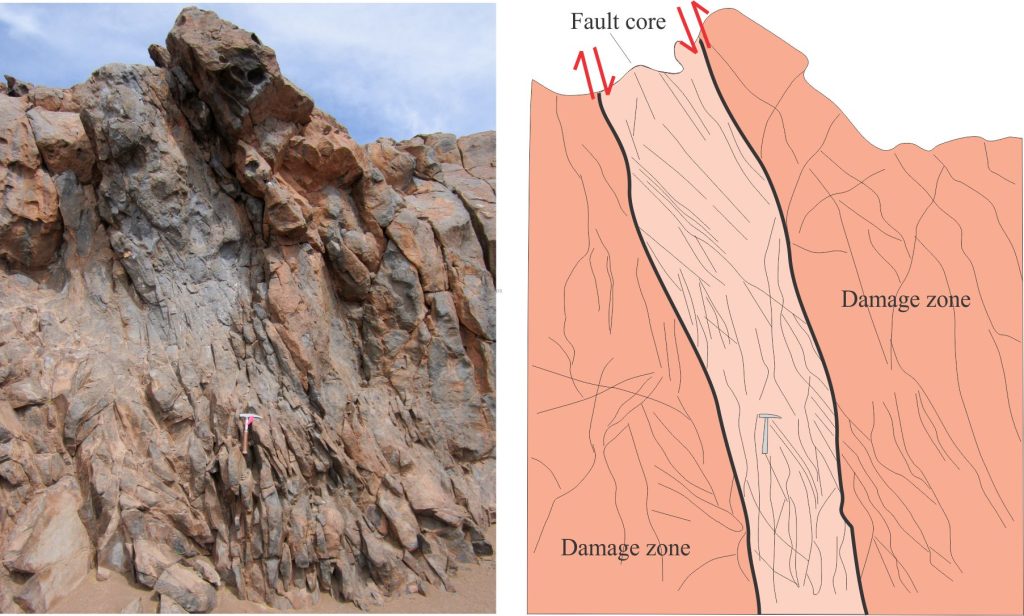
The permeability of the damaged zone will depend on the degree of fracturing and the three-dimensional interconnectedness of fractures; in highly fractured zones the bulk permeability may be greater than that of the fault core. Grain breakage and smearing of softer lithologies will tend to reduce permeability. If cataclasis produces much fine-grained material, the damaged zone may become a barrier to flow.
Permeability snapshots in time
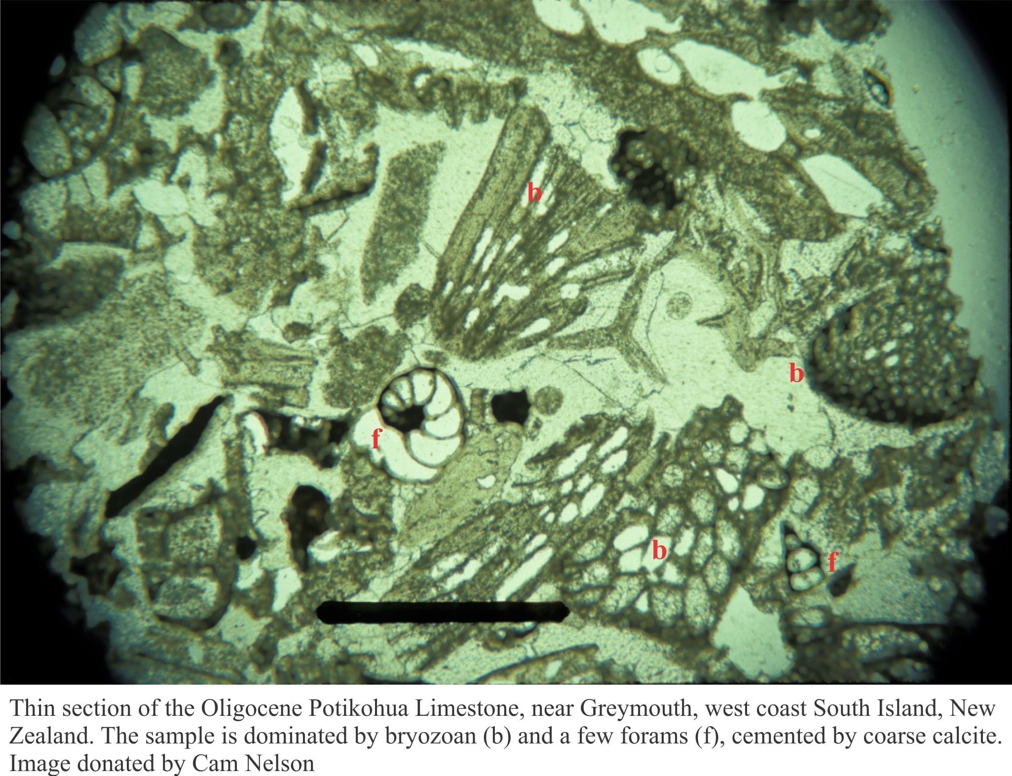
The foregoing discussion deals with the early stages of fault development and fault permeability. However, faults, like their host rocks, change with increasing burial depth, temperature, pressure, and the evolving composition of fluids that flow through their conduits. In some cases, fluid flow through the core and damage zone will promote alteration of the host rock, like that shown in the andesite example above. Other important changes to fault permeability involve the precipitation of minerals in the core and damaged zone; two of the most common precipitates are quartz and calcite. Precipitation depends on the degree of saturation for a particular mineral – it also depends on a continued supply of solute via advective flow. Crystal growth usually begins along fault and fracture walls, gradually filling the open cavities. At some point in this process, advective flow will be impeded, and continued precipitation will depend more on solute diffusion along crystal boundaries. At this stage the fault has become a barrier to fluid flow.
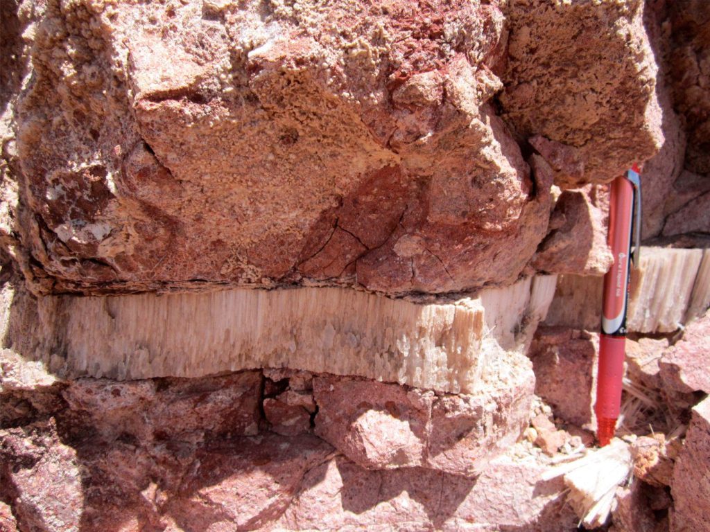
Fluid flow in faults may be episodic. An example illustrated by Louis et al., (2019), considers pulses of fluid flow initiated by episodic seismic (fault) activity, resulting in precipitation of clays and other silicate minerals that eventually sealed the fault conduits.
The mechanical behaviour of faults also changes as they fill with mineral precipitates; in some situations, the mineral-cemented core and damage zone may become stronger than their host rock.
3-D variability in fault permeability
The permeability along a fault can be highly variable for the following reasons:
- The dimensions of fault cores and damaged zones will vary along a fault, depending on differences in mechanical strength (e.g., cemented sandstone versus shale), the magnitude of the stresses, and fracture plane asperities. For example, segments of a fault may contain only a simple core; other segments may contain broad damage zones of brecciation and fracture networks.
- Changes in the production of comminuted rock originating from brecciation and grain breakage.
- Soft-rock smearing in layered successions.
- Changes in the amount of mineral precipitate infill.
- Episodic movement along the fault.
Other posts in this series
Sedimentary basins: Regions of prolonged subsidence
The rheology of the lithosphere
Isostasy: A lithospheric balancing act
The thermal structure of the lithosphere
Classification of sedimentary basins
Stretching the lithosphere: Rift basins
Nascent, conjugate passive margins
Thrust faults: Some common terminology
Basins formed by lithospheric flexure
Basins formed by strike-slip tectonics
Allochthonous terranes: suspect and exotic
Source to sink: Sediment routing systems
