This post is part of the How to… series
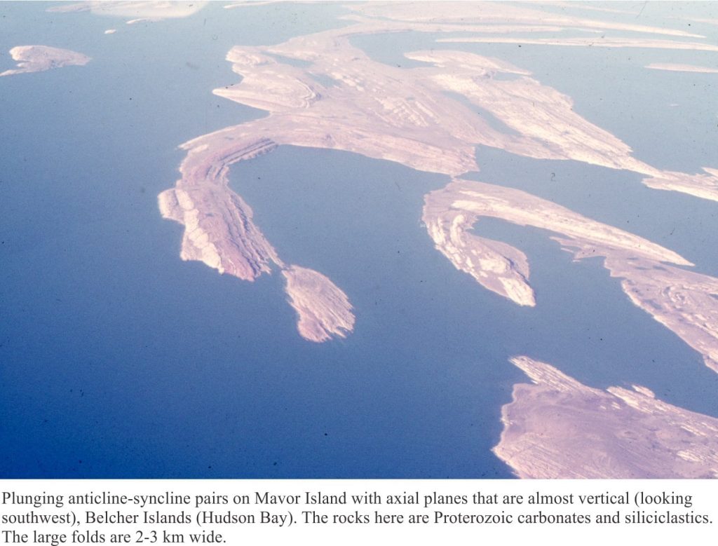
Folds invoke a sense of awe, of some gargantuan, earth-bound push-and-shove. A hand bending and buckling rock with plasticine ease, like some Wallace and Grommet joke. Folds the size of your finger or entire mountains. They are windows into the forces that shape our world.
An analysis of folds is central to unravelling the structural complexities of solid Earth, the history of mountain belts, the formation and emplacement of Earth resources. And like any scientific analysis we need some terminology. Fold terminology is pragmatic; it is based primarily on what one commonly observes at the rock face or hillside. Its utility, combined with simple geometric rules, enables us to project structures beyond the immediately observable, to learn that small outcrop-scale folds formed sympathetically with much larger structures, or decipher the relative movement of fault blocks.
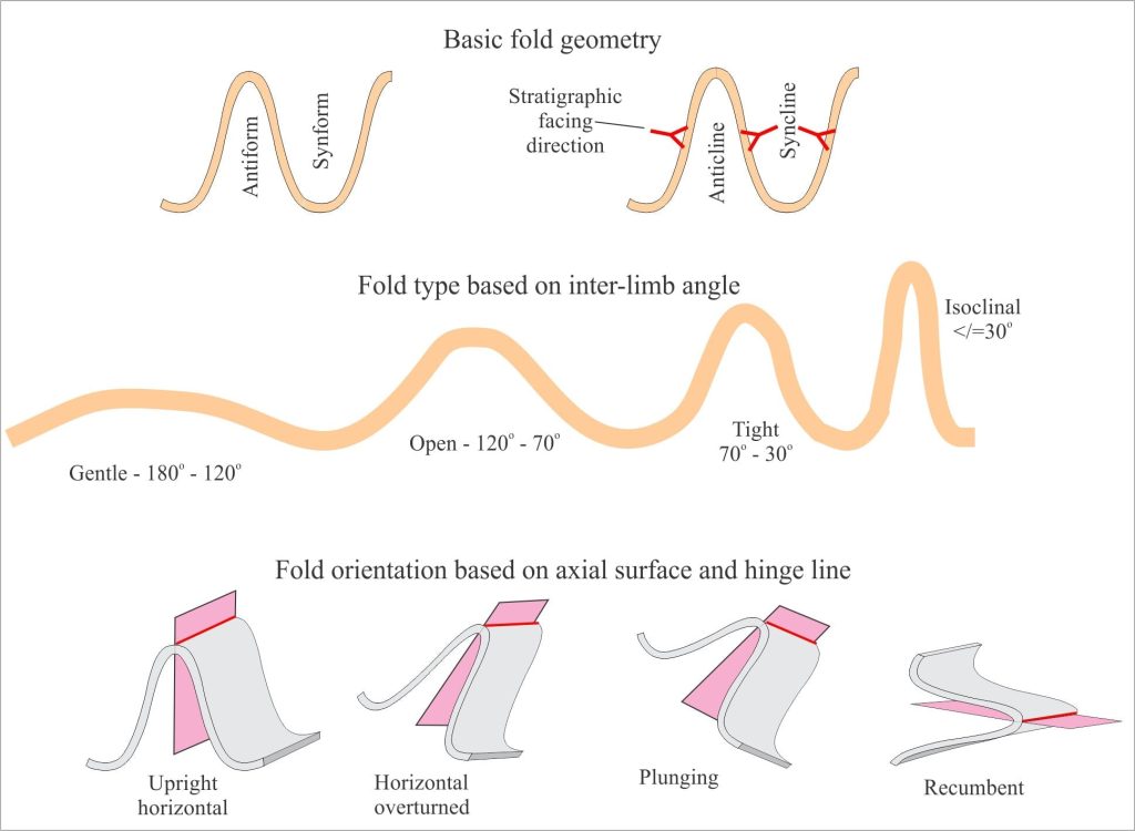
Although there are a myriad fold shapes and sizes, most can be described as variations of two basic forms: synforms which are concave upward folds, and antiforms which are convex upward. If we know the stratigraphic order of folded layers then we can use the more common names: anticline for folds that are convex in the direction of younging, and syncline for those that are concave in the direction of younging. If we do not know the younging or facing direction, a common problem in metamorphic rocks, then we must use the synform-antiform terminology.
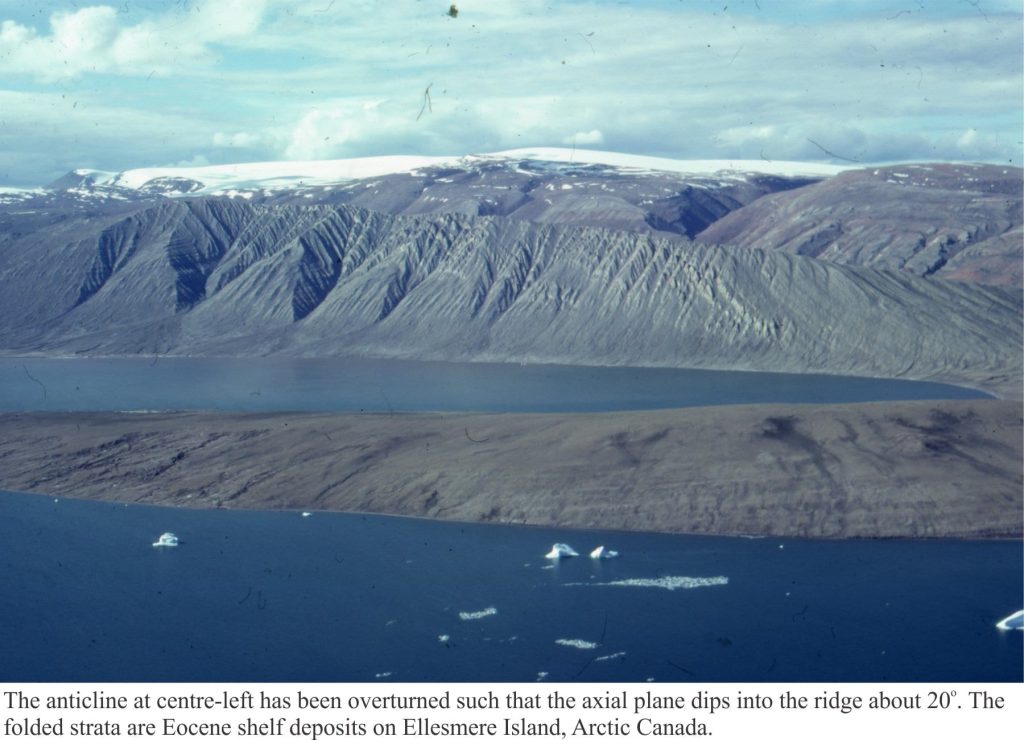
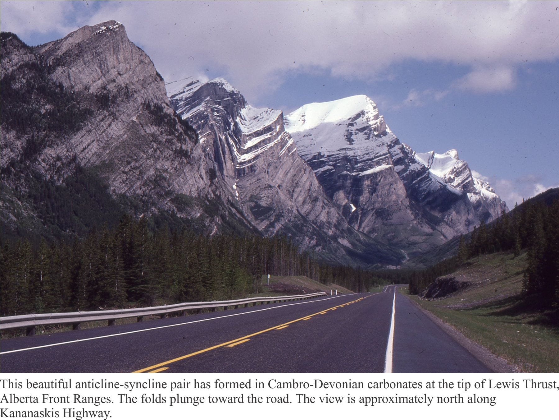
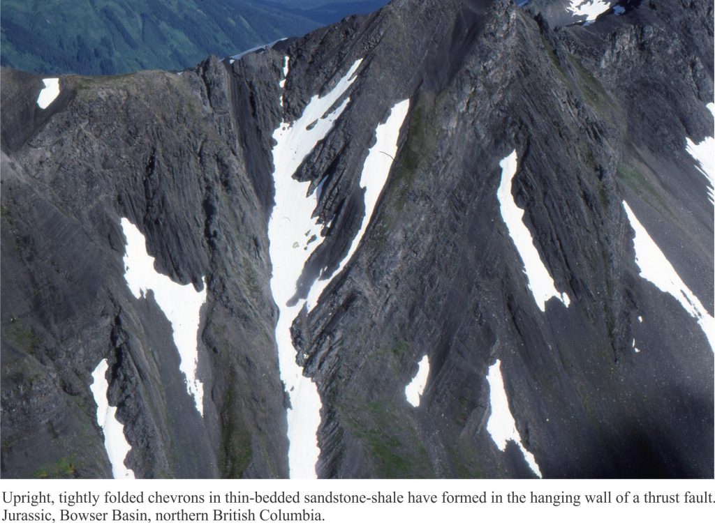
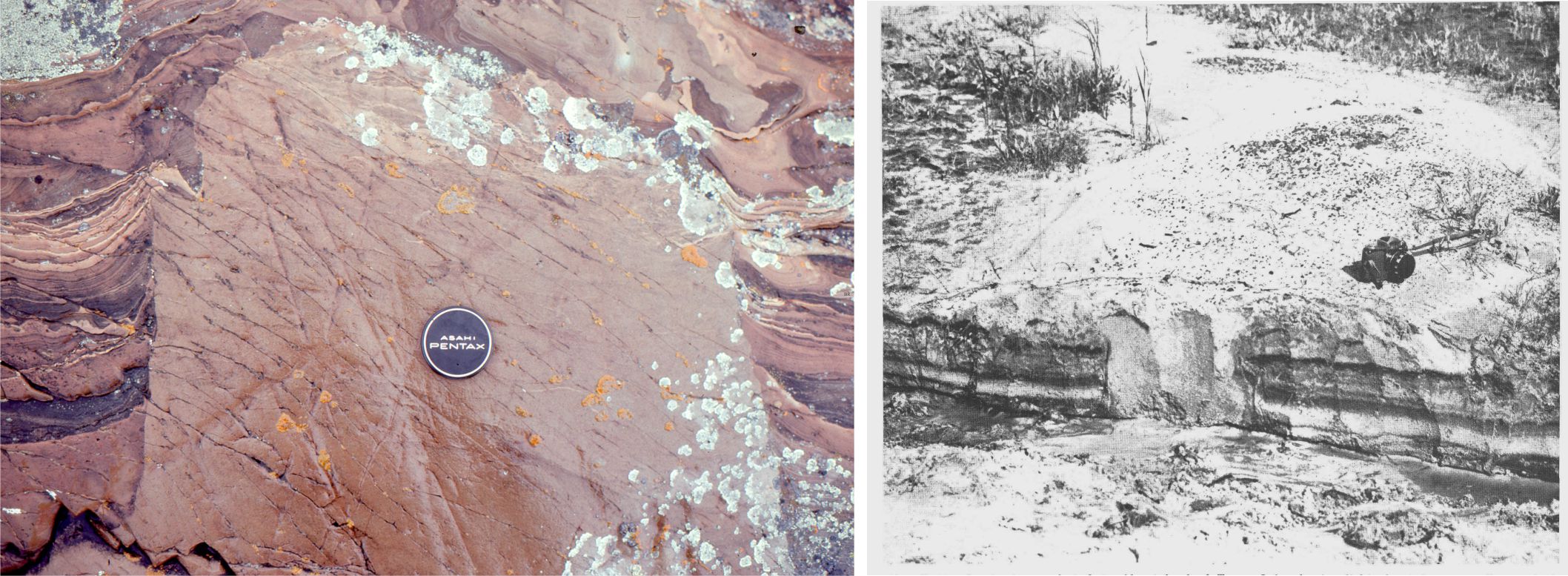
The diagram above also shows some basic fold orientations and the inter-limb angles that determine the tightness of a fold. Have a look at the images at the bottom of this page for examples.
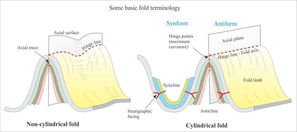
All folds have hinge points – the point (or narrow zone) of maximum curvature on a folded surface. Points of maximum curvature connected along a fold surface will define a hinge line; the hinge line may be straight or curved. However, to define the orientation of the fold uniquely, we need one other measure – the axial surface. The axial surface is defined by connecting all the hinge lines for each layer in the fold. The axial surface may be curved or planar – if it is the latter, we call it an axial plane. The orientation of an axial plane is determined by its strike and dip. Note that hinge lines also lie on the axial surface/plane.
If a hinge line is straight, it is called a fold axis (that must also lie on the axial plane). A fold axis is an imaginary straight, or nearly straight line that, when moved parallel to itself, will recreate the fold. This property distinguishes fold axes from hinge lines. The brief animation here shows diagrammatically the generation of a fold about the locus of a fold axis.
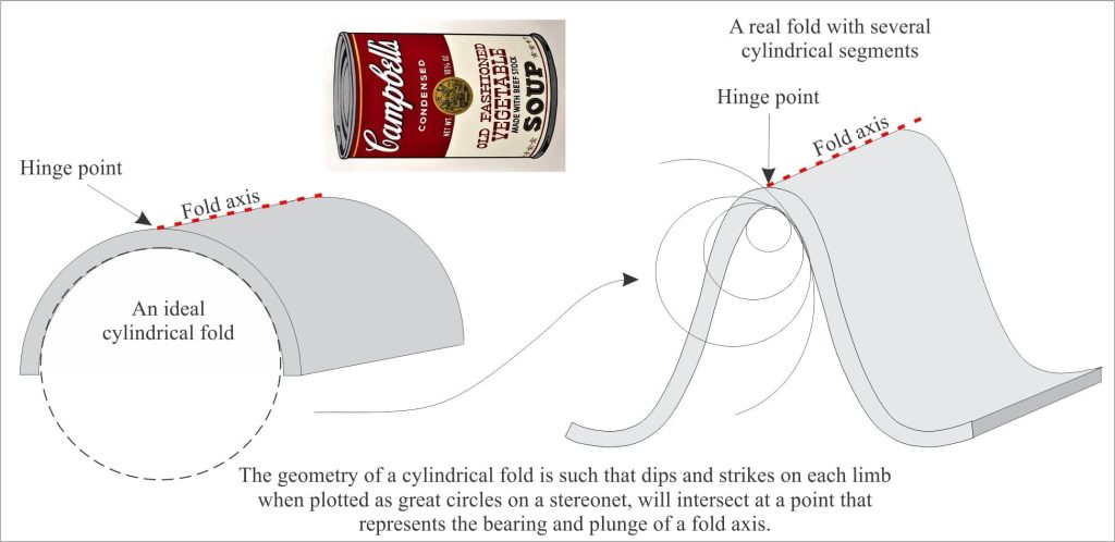
We can use the geometric identity of a fold axis to define two other classes of folds: cylindrical and non-cylindrical folds. All cylindrical folds have fold axes; all cylindrical folds have axial planes (non-cylindrical folds have axial surfaces). An ideal cylindrical fold is analogous to a soup can with both ends removed. Of course, real folds rarely look like cylinders – most have some degree of hinge-line curvature. But most folds can be divided into straight-line or nearly-straight line segments, such that aspects of cylindricity can be identified in each segment (as in the diagram).
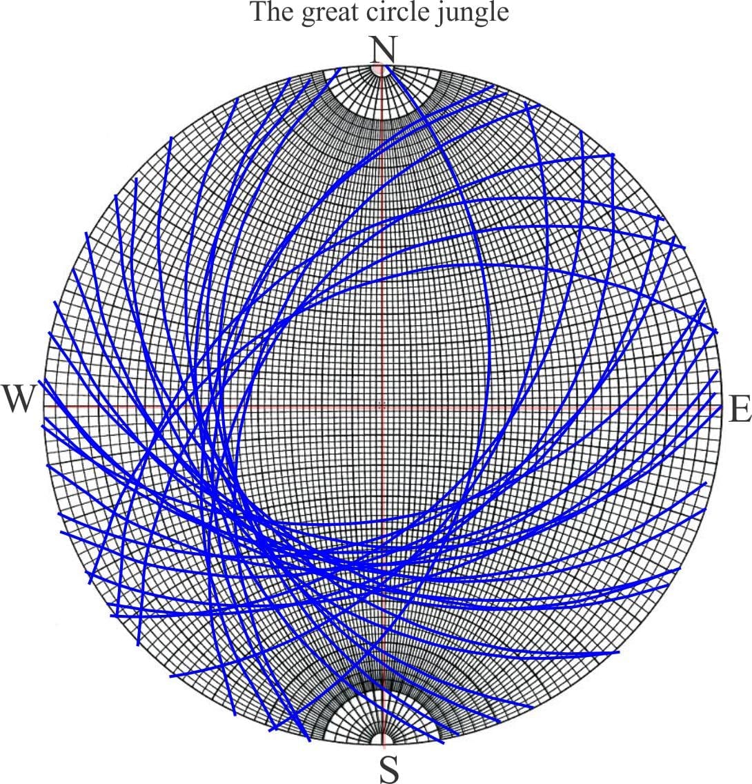
This may sound a bit contrived – actually it is – but it provides us with a sensible approach to fold analysis, particularly using stereographic projections. In the simplest case, a dip and strike measurement on each limb of a cylindrical fold will plot on a stereonet as two great circles, the intersection of which is a point that represents the trend and plunge of the hinge line, or fold axis. We can begin to make sense of more complex geometries in large-scale folds if we analyse each cylindrical fold segment in this way. The stereographic projection method of fold analysis will be described in another post.
Some other posts in this series:
Solving the three-point problem
Stereographic projection – the basics
Stereographic projection – unfolding folds
Stereographic projection – poles to planes
The Rule of Vs in geological mapping
Faults – some common terminology
Thrust faults: Some common terminology
Some older, but incredibly useful texts on folds and structural geology:
G.H. Davis and S.J. Reynolds. 1996 Structural geology of rocks and regions. John Wiley & Sons, Inc. New York, 776 p.
B.E. Hobbs, W.D. Means, and P.F. Williams, 1976. An outline of structural geology. John Wiley & Sons, Inc. New York, 571 p.
J.G. Ramsey, 1967. Folding and fracturing of rocks. McGraw-Hill Book Co., New York, 560 p.
J.G. Ramsey and M.I. Huber. 1987. The techniques of modern structural geology, v.2. Folds and fractures. Academic Press, London, 381 p.
