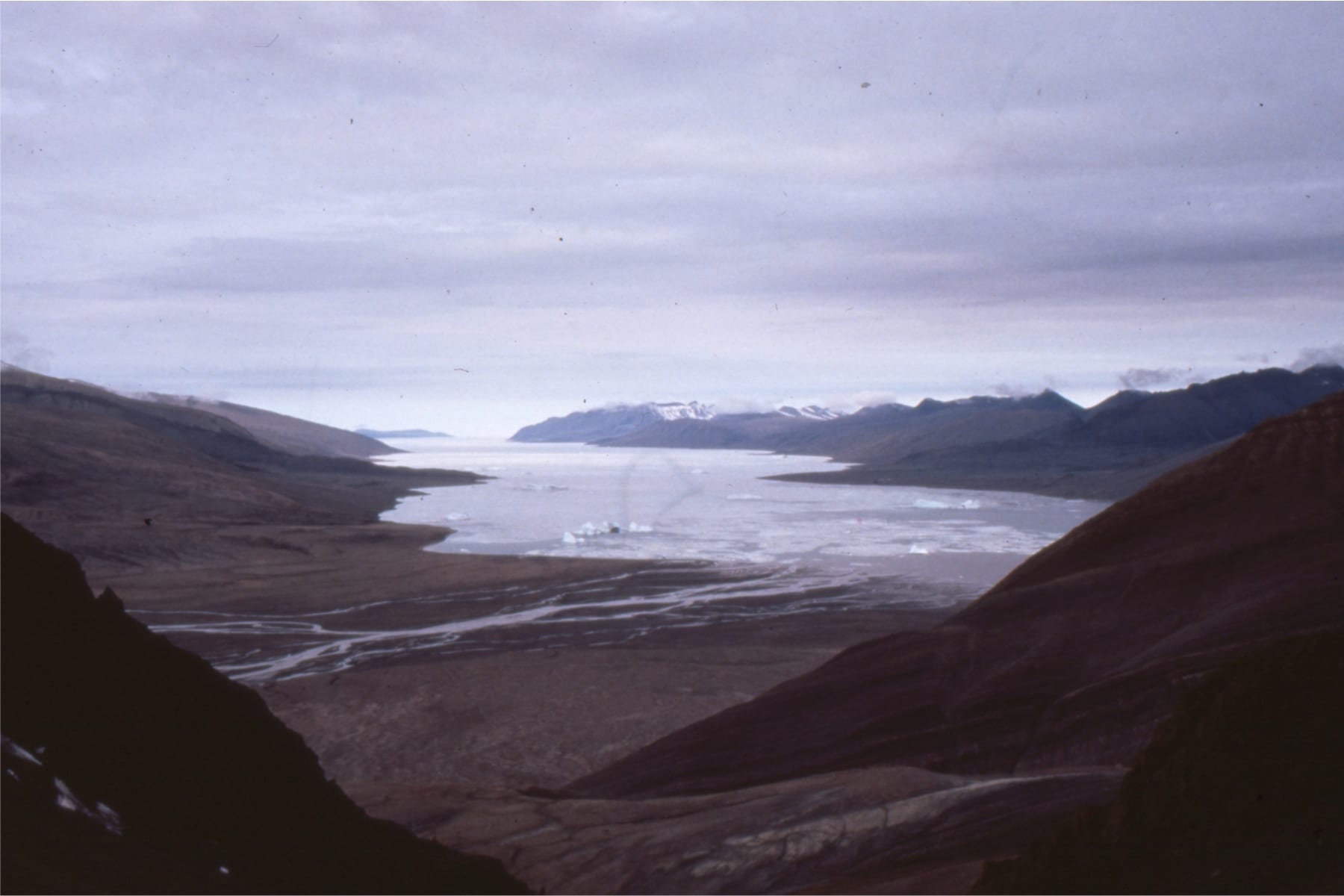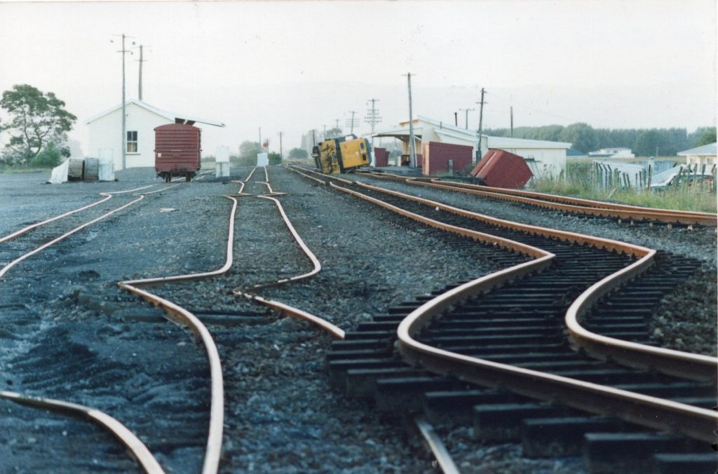
A fault is a plane or linear zone of displacement, where rocks on one side of the plane slip past those on the other side. They represent the brittle failure of rock when strain rates are high, a condition usually associated with earthquakes. They form at Earth’s surface and at any depth in the crust where brittle failure is possible. The amount of slip ranges from millimetres to 100s of kilometres and can be generated in a single event or cumulatively in multiple events. An example of the latter is the 480 km lateral displacement across the Alpine transform fault in New Zealand, that has been accumulating since the Early Miocene.
Anatomy of a fault
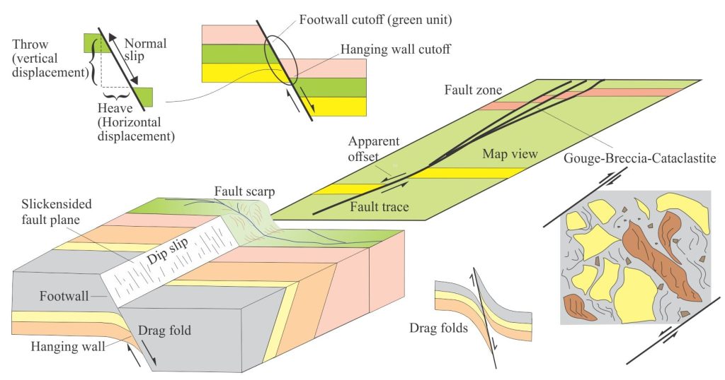
Faulting produces displacement across a surface. If the surface is planar, then we call it a fault plane. The orientation of a fault plane is described by its strike and dip. The surface map expression is a fault trace. Because maps are horizontal projections of geology, the bearing of the fault trace on a map will be a good approximation of its strike.
Exposed fault surfaces are subject to weathering and the effects of erosion, collapse of rock and sediment, and the development of soils. Fault scarp refers to this topographic expression of a fault surface. The actual fault plane on such exposures will not be visible. Measurements of displacement will be problematic on degraded scarps. Trenching across the strike of degraded scarps will help provide more useful information on fault dynamics.
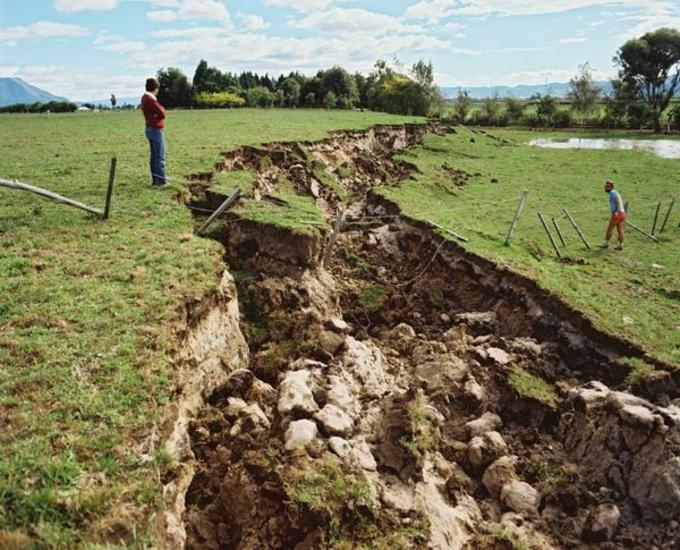
Faulting may produce a single strand, or the strain (deformation) may be distributed across a zone of closely spaced faults; the width of these fault zones ranges from a few centimetres to many 10s of metres. The development of fault zones depends to a large extent on the competency or strength of the rock; they are more common in weak rock and unconsolidated sediment. A characteristic feature of fault zones is the crushing and grinding of rock, producing much fine-grained material (fault gouge), cataclastite (indurated fault rock, clasts <10 mm), and fault breccia (larger angular blocks).
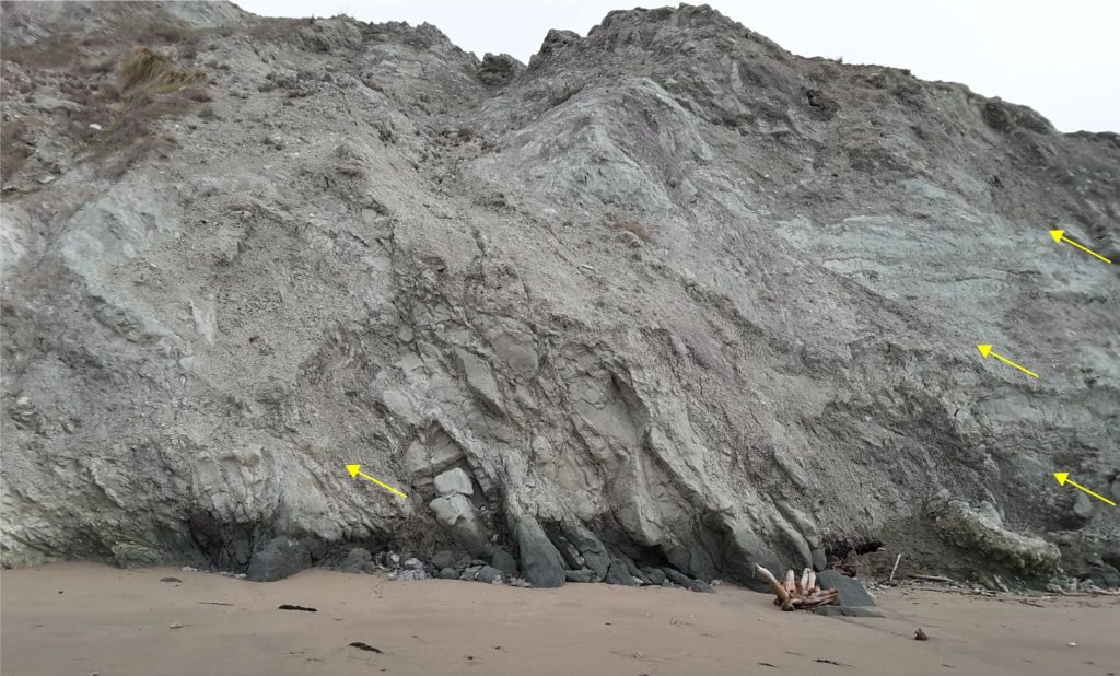
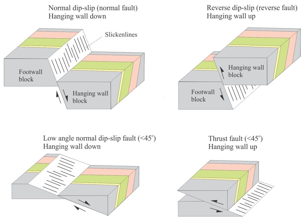
Displaced rocks on either side of a fault are described as footwall and hanging wall blocks, the relative displacement of which are important for fault classification. An easy way to remember which term applies – the footwall is what you stand on; the hanging wall is over your head.
A true measure of fault block displacement is its slip. Any other measures will be components of slip, or apparent slip. The vertical and horizontal components of slip (throw and heave respectively) are determined by identifying footwall and hanging wall cutoffs of suitable markers – specific beds or rock units that can be traced from the footwall to hanging wall blocks. Foot wall and hanging wall cutoffs refer to the point where a layer is truncated by the fault plane. Fault plane structures such as slickenlines will provide the other component of slip – its direction.
Piercing points are a special kind of cutoff, that refer to the displacement of specific objects of linear structures that can be traced from the foot wall to hanging wall. The line connecting the two points gives a measure of net displacement, from which dip-slip displacement can be calculated using simple trigonometric functions.
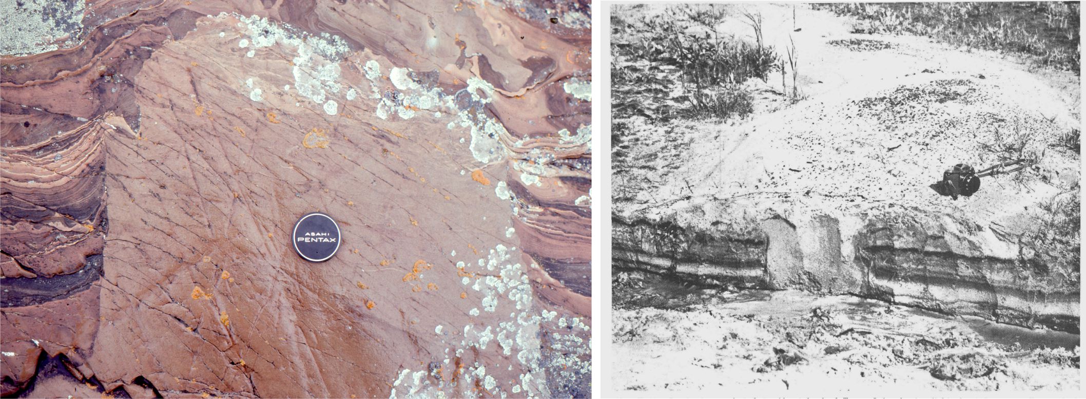
Polished fault planes are called slickensides. Useful structures on slickensided planes are parallel arrays of striae and grooves, or slickenlines. Slickenlines are valuable indicators of fault slip. If they are normal to fault plane strike, then slip was either up or down dip; if parallel to strike then displacement was strike-slip. Oblique versions of these end members have components of dip-slip and strike-slip.
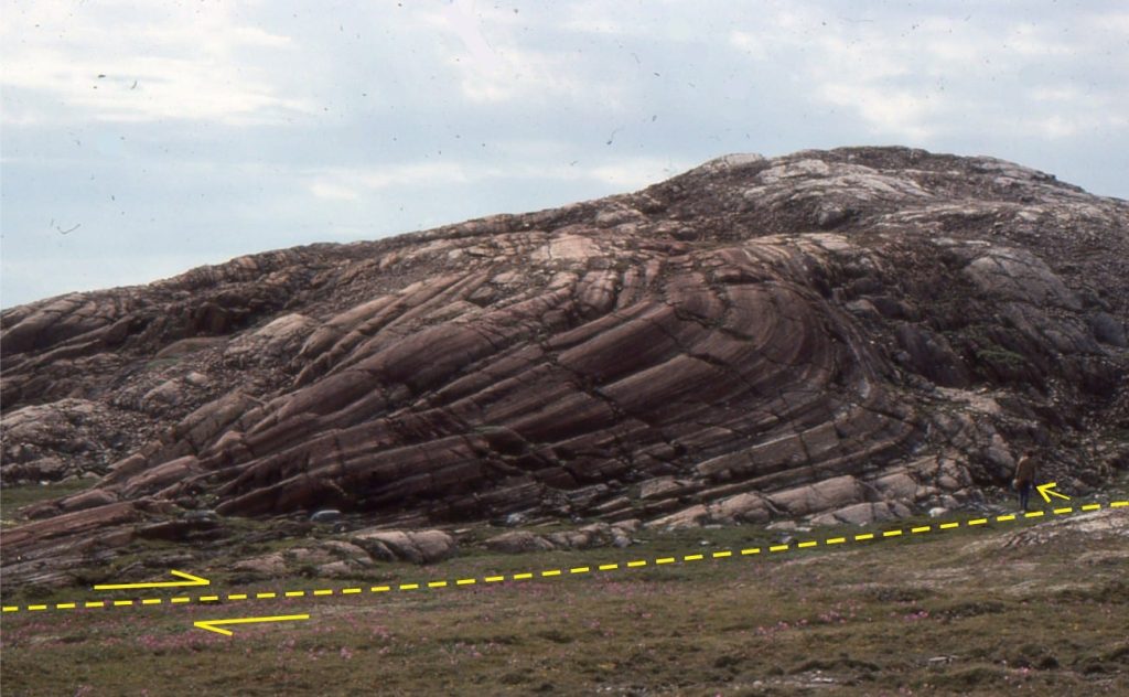
Drag folds and tension gashes also provide good kinematic indicators of fault displacement. They are the result of shear as one block slides past another (also called parasitic folds).
Apparent fault offset
The map view in the above diagram shows a fault offset that might be construed as strike-slip. Is this true strike-slip displacement, or an apparent displacement caused by the geometric relationship between a dipping fault plane and dipping strata? The following example illustrates this problem.
In the example, slickenlines indicate that actual slip is at right angles to the fault plane strike (i.e. it is a normal dip-slip fault). The up-faulted block is eroded incrementally until the fault plane is no longer exposed and the topography is congruent with the down-thrown block. A short video shows the progressive development of an apparent lateral displacement of the yellow and green marker beds as the land surface is eroded. The cautionary note from this simple demonstration is that if true slip cannot be determined, the displacement must be described as an apparent offset; also referred to as fault separation.
Fault types based on slip
The classification of faults is based on slip direction. We define three main categories: dip-slip, strike-slip, and oblique-slip. Further subdivision of these groups is based on fault plane dip. Fault planes dipping < 45o include low-angle normal faults and thrust faults.
Dip-slip
Most normal faults dip >60o; thrust faults (low-angle reverse faults) commonly dip 30o and less. The hanging wall is down in normal faults, and up in reverse faults.
Strike-slip
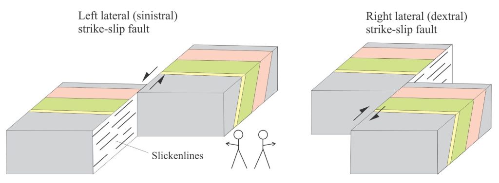
Strike-parallel fault plane slip is described as right-lateral (dextral, or right-handed) or left-lateral (sinistral, or left-handed). The relative displacement is determined with the fault plane facing the observer such that the block on the far side of the fault moves right of left.
Oblique-slip
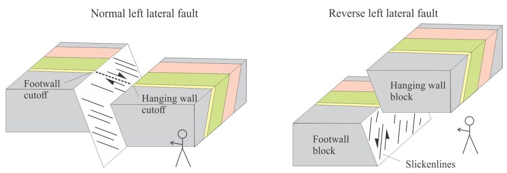
Many faults are defined by combinations of dip-slip and strike-slip displacement. Thus, there are normal and reverse faults that will also have components of right-lateral (dextral or right- handed) or left-lateral (sinistral or left-handed) slip. The same rule for left-handedness in strike-slip faults applies here. Actual slip can be determined from slickenlines and fault plane cutoff points, as shown in the sketch below.
Listric faults
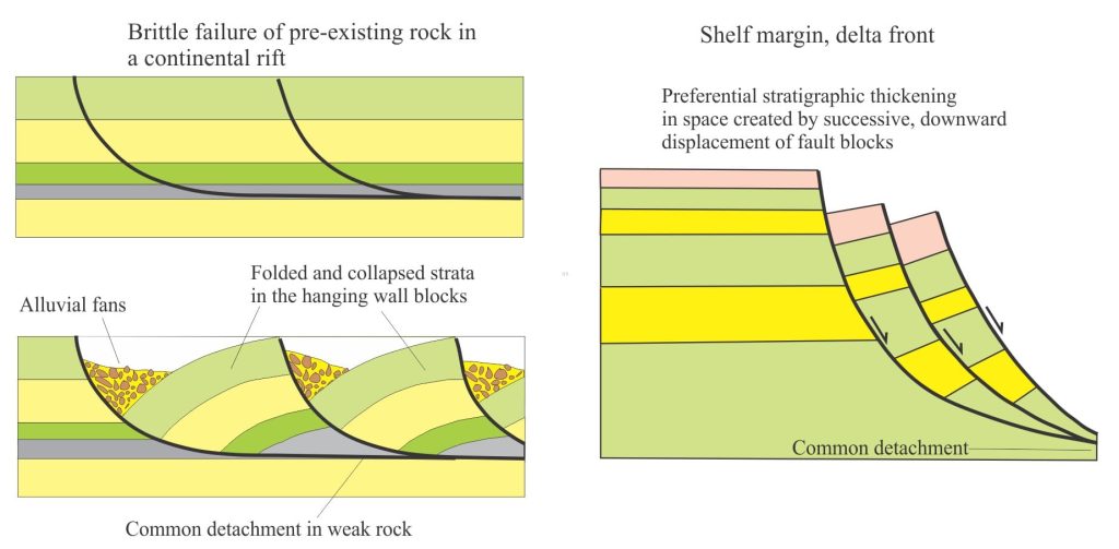
Listric faults have normal dip-slip (or oblique-slip) displacements but are characterized by concave upward fault surfaces. They have steep dips near the surface, flattening at depth in a detachment surface that is common to other faults. Like most other fault types, they can occur at crustal scales (they are characteristic of continental rifts), or at smaller scales in depositional systems such as deltas. This style of rotational displacement is also common in slumps.
Listric faults are a product of extension. During displacement, the hanging wall block either rotates towards the foot wall or collapses into the space created by extension. Episodic displacement, a common occurrence, produces increasingly angular discordances at the hanging wall block surface, resulting in multiple angular unconformities in overlying stratigraphic packages. The term growth fault is often used where deposition is relatively continuous during fault displacement; stratigraphic units are commonly thicker over the displaced hanging wall block because of the increased accommodation.
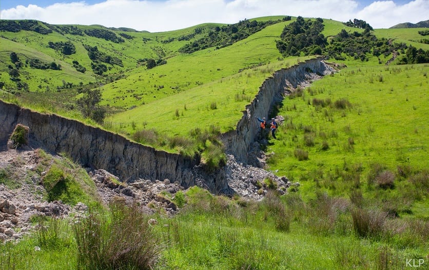
Thanks to Dr Kate Pedley, University of Canterbury for permission to use the 2016 fault scarp image. kate.pedley@canterbury.ac.nz Check out her Twitter page @KPedleyNZgeol
Other posts in this series on Common Structure and Mapping Problems
Solving the three-point problem
Stereographic projection – the basics
Stereographic projection of linear measurements
Stereographic projection – unfolding folds
Stereographic projection – poles to planes
The Rule of Vs in geological mapping
Thrust faults: Some common terminology
Using S and Z folds to decipher large-scale structures
Cleavage and cleavage-bedding intersections
The kinematics of deformed rock
