CCS – what is it?
Carbon dioxide is a significant by-product of oil and natural gas production at the well-head, hydrocarbon and coal combustion (especially in power generation) and several manufacturing industries (e.g. cement). Carbon Capture and Storage (CCS) involves technology that captures CO2 produced by these industrial processes and stores it underground. In doing so, CCS technology attempts to prevent the CO2 from being released into the atmosphere. From the point of view of potential climate change it seems like a sensible thing to do. However, CCS does have its detractors who argue primarily that either it doesn’t matter how much CO2 enters the atmosphere, or that the costs far outweigh the benefits. Indeed, the cost of CCS programs is high. Regardless, the science of CCS is fascinating.
Massachusetts Institute of Technology CCS program provides an up to-date global list of active and planned, commercial, non-commercial and pilot projects (most are in the planning stage).
Statoil’s Sleipner project in North Sea was the first fully commercial CCS program, beginning in1996. Apparently tax incentives (or disincentives) were a prime motivation for the project. Natural gas and condensate in the Sleipner field contain up to 9% CO2. Almost 16 million tonnes of captured CO2 has been pumped 800-1000m below the sea floor into saline rock formations.
The recently commissioned Boundary Dam coal-fired power station (2014, Saskatchewan) illustrates some of the pros and cons of commercial CCS projects. The total cost was a huge $1.3 billion; incentives included government support and tax incentives. It is anticipated that up to 90% recovery of CO2 will eventually reduce emissions by 1 million tonnes/year; up to 100% of sulphur dioxide is also removed. Captured CO2 will mostly be used in Enhanced Oil Recovery programs. Capture at this facility uses about 20% of the total power produced.
The Sleipner and Boundary Dam projects illustrate two of the most common types of geological storage (also referred to as sequestration); storage in deep geological formations, and Enhanced Oil Recovery (EOR). We will look briefly at both types, but first a quick review of some relevant properties of CO2.
Dry Ice etc.
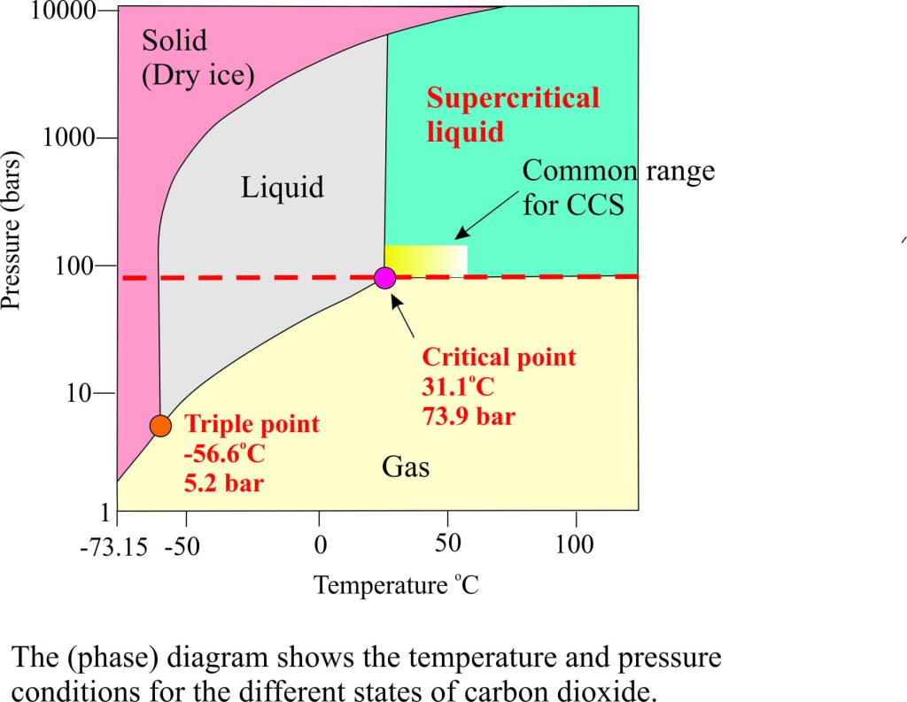 Most of you will be familiar with carbon dioxide as a gas or (theatrical) dry ice. At room temperature dry ice sublimates directly to CO2 gas – there is no intervening liquid phase under these conditions. However, the best way to move CO2 around in pipes and rock reservoirs is in a liquid phase, specifically as a supercritical liquid. The diagram opposite, known as a phase diagram, shows the relationship of CO2 in its gas, solid and liquid phases according to a range of temperatures and pressures. The triple point is where all 3 phases can exist together. However, the important point for our discussion is the critical point, where at a temperature of 31.1C and about 73 atmospheres (equivalent to 1071 psi, or 7.39MPa) liquid CO2 changes to a supercritical liquid. A supercritical liquid has properties somewhere between a gas and a liquid. For CO2 these properties include:
- High solubility in oil and water
- Density similar to the liquid phase but much lower viscosity; the latter property enhances flow through pipes (transport)and through porous rock.
- Low surface tension.
The pressure and temperature conditions mean that for the supercritical liquid state of CO2 to be preserved it must be buried on average 800m and deeper for storage or EOR operations; at shallower depths (and lower pressures) it will convert to a gas.
Enhanced Oil Recovery
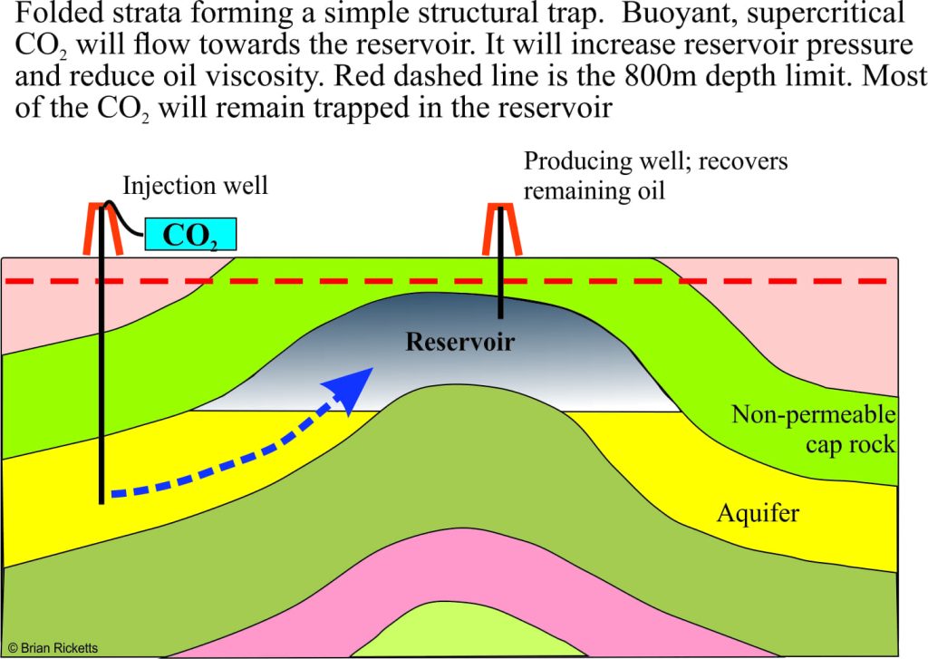
Enhanced oil recovery is generally used in reservoirs that are either under-pressured or depleted; it’s like trying to squeeze the last drop from the reservoir. Carbon dioxide has been used in EOR operations since the 1970s. It’s not surprising then that most CCS pilot projects are directed at EOR. Carbon dioxide is injected as a supercritical fluid into offset wells that are known to have good hydraulic connection with the producing oil/gas reservoir. This has the effect of increasing reservoir pressure and decreasing hydrocarbon viscosity. Some CO2 will be produced with the oil, but most will stay in the reservoir.
Geological storage
Two of the most common types of storage utilized in CCS projects are depleted oil and gas reservoirs, and other geological structures that satisfy the following conditions:
- Sufficiently thick, porous and permeable aquifers such as sandstone and limestone.
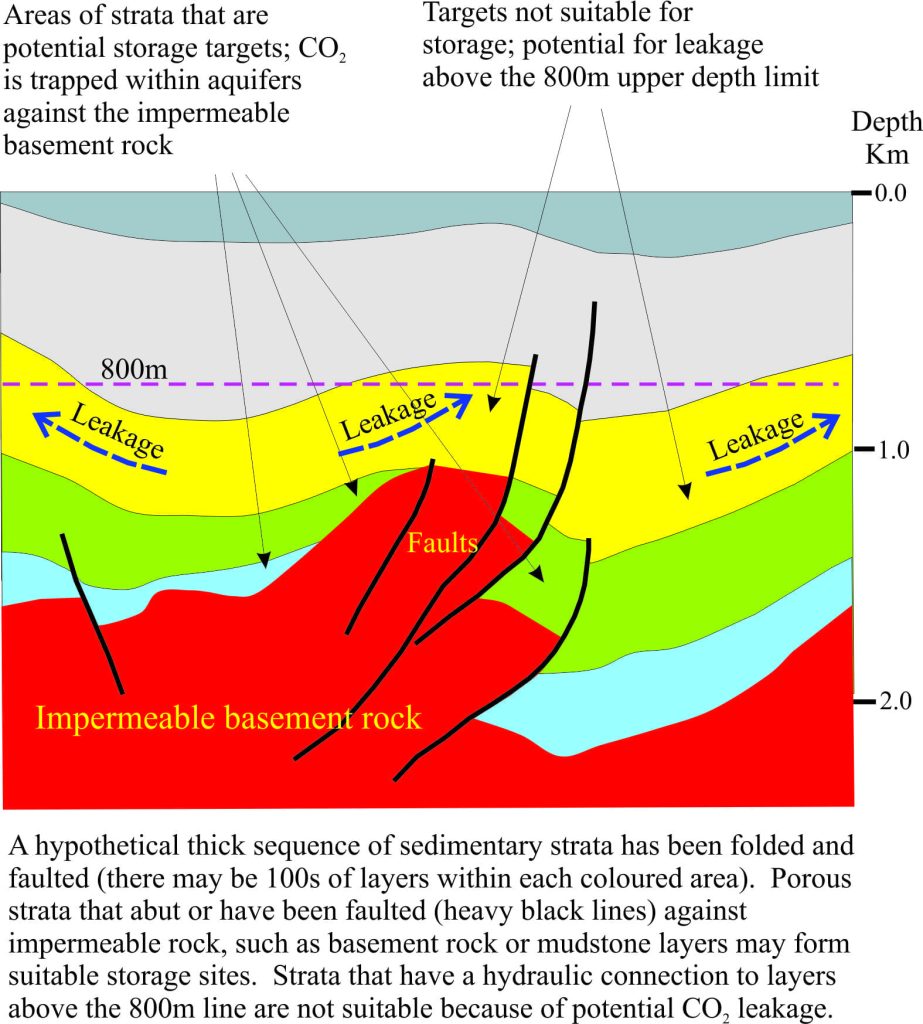
- Barriers that prevent flow or leakage of fluids, or trapping mechanisms, include impermeable layers such as mud rocks or salt, and structures such as folds and faults, or combinations of these. A good trap will prevent the gas from escaping to the atmosphere.
- Aquifers and reservoirs must be deeper than about 800m.
- Sites should be remote from active faults to avoid breaching of traps.
Depleted oil & gas reservoirs
An advantage of using this kind of structure is that there is generally a lot of geotechnical information available because of commercial oil production. Supercritical CO2 is significantly less dense than saline water and hence more buoyant. As the CO2 is pumped into the now disused reservoir it will displace the saline water and any remaining oil (some CO2 will also dissolve in the water). The reservoir trapping mechanism(s) that prevented leakage of the original oil, will also operate to prevent leakage of the stored CO2.
Other geological structures
The principles that apply to disused oil reservoirs also apply to geological regions that do not contain oil and gas. In the diagram above, the flow of stored CO2 in the blue and green sedimentary units is prevented where the aquifer layers abut impermeable basement rock and also where the aquifer has been truncated by faults; these are good traps for CO2 storage. However, aquifers in the yellow unit that extend above the 800m depth limit would be excluded because of the risk of gas leakage.
Storage via chemical reactions in buried rock
Carbon dioxide is highly soluble in water and has the potential to be involved in chemical reactions that form common minerals like calcite. Although recognized as a possible mechanism for sequestering carbon dioxide it has been generally understood that the rates of mineralisation would be very slow. A new study by a multidisciplinary research group working in Iceland injected CO2 and water together into old basaltic lava flows and sediments (400 to 800m depth). They discovered that about 95% of the injected CO2 had reacted over a two-year period with Ca (calcium), Fe (iron) and Mg (magnesium) dissolved from the basalts to form stable carbonate minerals. The overall cost of this process is significantly less than standard CCS methods because it avoids the physical separation of captured CO2.
Postscript
Improvements in technology for all aspects of CCS and EOR will no doubt continue, making CO2 capture less expensive and more efficient. Chemical sequestration like that undertaken in Iceland looks promising although basalt aquifers may be in short supply. For greenhouse emissions, Carbon Capture is not the silver bullet that some might hope it to be, but in conjunction with other technologies it does have the potential to help reduce the rate of CO2 emissions.




3 thoughts on “Geological Trappings; Carbon Capture and Storage”
I am working on Business Development for SEG SEAM corporation. The project I will be championing is CO2 sequestration. I would like to communicate more on this topic, is this discussion available as a pdf or published particle that I can get. I helped prepared a geocellular simulation for the Sliepner filed from public domain data an d presented the results at a SPE environmental conference in 2003. ( Simulation Study of CO2 Sequestration in a North Sea Formation’ SPE/EPA/DOE Exploration and Production Environmental Conference, 10-12 March,2003, San Antonio, Texas)
Pingback: Oil & Gas Sciency: What do you know about Geological Trappings; Carbon Capture And Storage? | The Mozambique Resources Post
You should not repost this without permission. But I see you already have!