This post focuses on sandbox models and what they tell us about the mechanics and kinematics of orogenic wedge development.
The catchall term orogenic wedge refers to:
- A supracrustal wedge or prism of rock, deformed and horizontally shortened by thrust faults and associated folds, and
- Formed across the upper plate at compressional plate boundaries.
- The term includes the well documented forelandfold-thrust belts that develop in continental crust during episodes of mountain building (orogeny), and

- Their oceanic analogues in accretionary prisms that form above subduction zones. Material in this type includes sediment and fragments of oceanic crust scraped from the subducting plate and accreted to the upper plate.
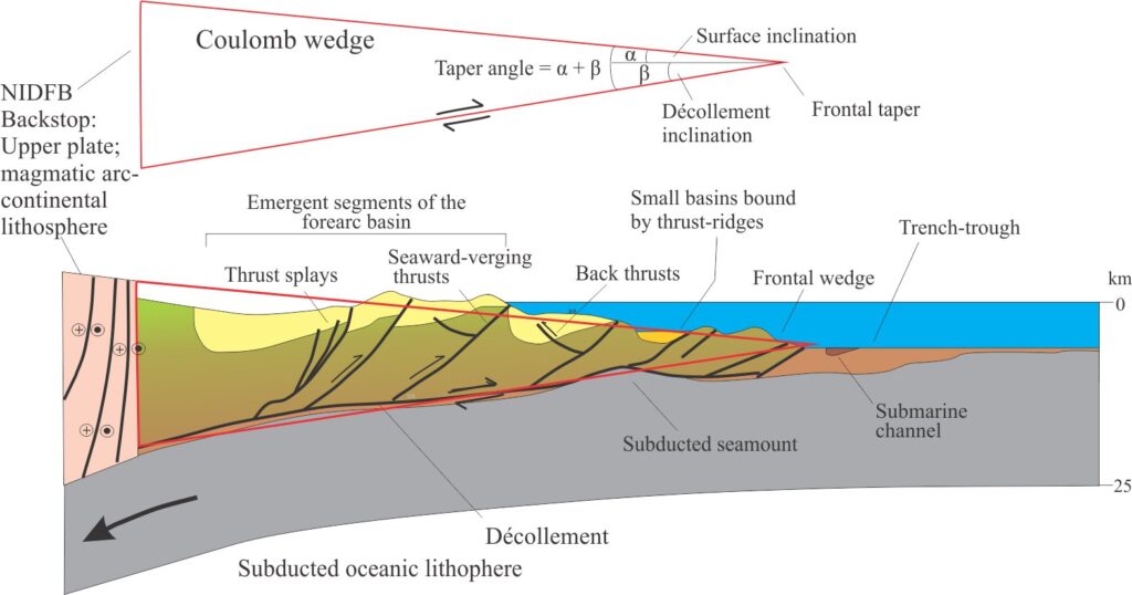
- The application of the wedge concept is based on the overall geometry of the deformed panel of rock; for foreland fold-thrust belts the wedge tapers towards the foreland, and in oceanic accretionary prisms towards the subduction zone.
- The wedge backstop is assumed to be relatively rigid – a volcanic arc or uplifted crust backing accretionary prisms, and uplifted continental crust in the case of fold-thrust belts. For example, the hinterland to Albert foreland thrust belt is the Omineca metamorphic core complex.
- In both types, thrusts verge predominantly towards the wedge toe (pointy end), that in fold-thrust belts corresponds to the triangle zone. Shortening across the wedge is accomplished by telescoping of thrust panels.
The ‘wedge’ concept
Coulomb wedge theory was developed in 1773 C by Charles-Augustine de Coulomb (1736~1806) to predict the stability of excavated slopes with and without retaining walls; the theory applies equally to the stability of many kinds of construction such as tunnels or storage facilities where lateral stresses can lead to containment failure. The theory (also called the Earth pressure theory) combines geometric constraints and mathematical solutions to determine the stress components acting on these structures.
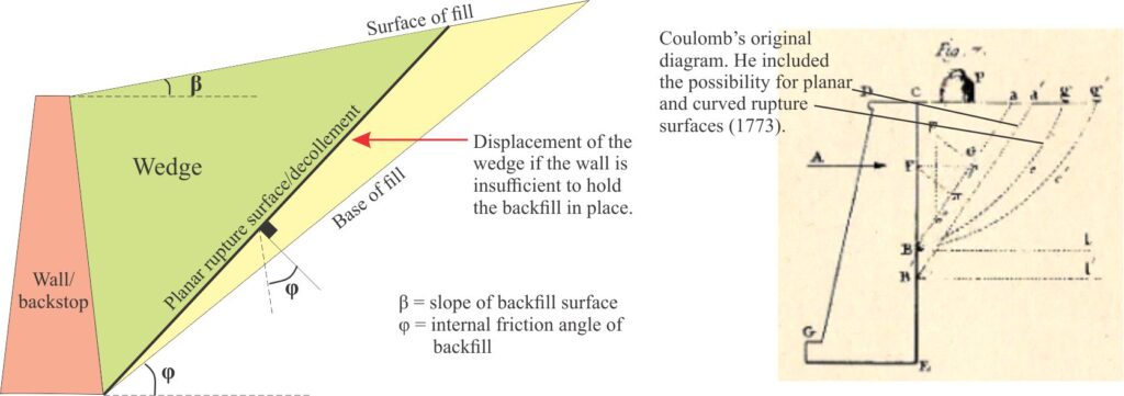
In Coulomb’s original diagram, and the more recent take on it, the wall acts as a backstop to the slope deposits or backfill sediment. These deposits will fail if the backstop under pressure moves away from the slope or rotates; the resulting wedge is bound by a planar or curved rupture surface. The assumptions in Coulomb’s analysis that are relevant to orogenic wedge models are:
- The slope material is isotropic and homogeneous; it has internal friction and cohesion.
- The rupture surface, or detachment (décollement), is planar (mathematically the simplest option).
- Friction is uniform along the rupture surface; the friction coefficient is tan θ.
- The wedge acts as a rigid body during translation – i.e., there is no internal deformation. However, most geological materials are not ideally isotropic which means that differential strain can develop during wedge translation. Coulomb’s theory does not predict the kind of deformation that may occur within a wedge.
Wedge dynamics
The application of Coulomb theory to orogenic wedges reverses the backstop movement – in the original model a retaining wall moves away from the slope and the principal horizontal stress is effectively extensional. For orogenic wedges located along collision or subduction boundaries the principal stress is compressional. Two of the earliest, and still the best descriptions of wedge mechanics and the mathematical expression of said mechanics are the papers by Davis, Suppe and Dahlen (1983, PDF) and Dahlen (1990) who use the analogy of a snowplow or bulldozer to develop their own analogue models.
Multiple observations of real deformed belts reveal three properties common to all orogenic wedges:
- A basal detachment (decollément) that dips toward the source of compression (hinterland); rocks beneath the detachment are not involved in the deformation.
- The developing structural architecture above the detachment indicates compression.
- Telescoping of thrust sheets and subsequent structural thickening of material above the detachment produces a wedge that tapers toward the foreland.
As the snowplow-bulldozer advances, material is accreted at the wedge toe until the taper angle reaches a critical value – the sum of the wedge slope dip (α) and the detachment dip (β). The critical taper represents an equilibrium state between the relative ease of deformation either within the wedge or displacement along the detachment. It is dependent on:
- The cohesive strength of the wedge materials.
- The nature of the detachment – is it planar, or easily deformed?
- Fluid pressure within the deforming material that, as Hubert and Rubey (1959) demonstrated in their iconic paper, has a significant control on rock deformation, particularly thrust faulting. Notably, Hubert and Ruby focused on subaerial conditions where water tables are commonly assumed to mimic and lie close to the land surface. However, large portions of oceanic accretionary systems are fully submerged which means that the effective internal strength of ocean floor sediment may be significantly lower than their subaerial counterparts.
If the taper is less than critical (i.e., the wedge slope is low) then the wedge will not advance and all the strain is transferred internally, manifested as thrust faults. If materials in the wedge are mechanically weak relative to the detachment, then accretion will produce a steeper wedge slope until a point is reached where deformation within the wedge is more difficult than that along the detachment; at this point strain will be transferred to the detachment. This kind of behaviour can be demonstrated in analogue models where deformation is transferred from detachment to wedge, and back again – the process is self-limiting.
Additional controls over wedge development include:
- Surface erosion of any part of the deformed belt that rises above sea level will tend to reduce wedge slopes and the critical taper.
- Tectonic erosion can also occur along the detachment where material is moved from one location to another part of the wedge (i.e., underplaying the wedge), or removed by subduction.
- There will be an isostatic response to wedge accretion because of the additional load on the lithosphere, manifested as subsidence. The isostatic response to surface erosion will be regional uplift.
Indenter and subduction analogue models

The architects of many 19th C “structural” experiments created sound foundations for all our more recent adventures in modeling. The likes of James Hall (1815), Henry Caddell, 1889, and Bailey Willis, 1894, were primarily concerned with duplicating structures like folds and faults that they had seen in the field. Their apparatuses advanced from bits of cloth squished between two sets of books, to sophisticated sand boxes with screw-driven plates driving the horizontal compression. Most of these early indenter (snowplow – bulldozer) experiments successfully reproduced the ductile response of folds and brittle behaviour of thrust faults above flat detachments. Some even produced (inadvertently) wedges of deformed strata (see excellent reviews by Graveleau et al., (2012, PDF); Schellart and Strak, (2016. The indenters in these models act as wedge backstops and move towards the taper (towards the foreland in real mountain belts). In-sequence thrusts verge in this direction. Back-thrusts also propagate in materials close to the backstop.

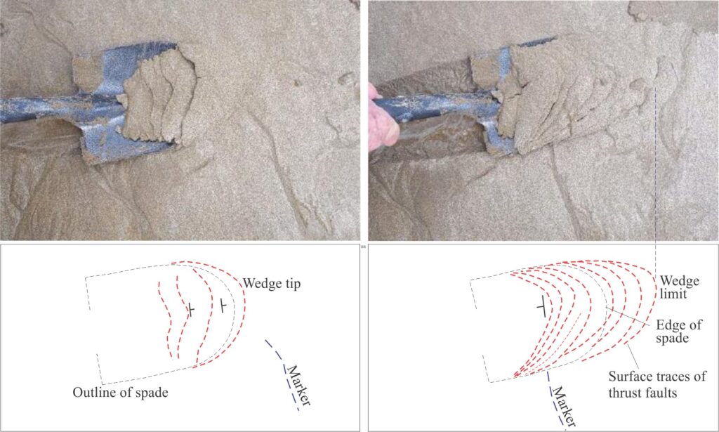
The indenter in the subduction model developed by Davis et al., (op cit) is stationary – it is the analogue for an island arc or continental fault-block backstop in the upper, lithospheric plate, beneath which oceanic lithosphere is subducting. The down-going oceanic plate was modeled as a movable Mylar sheet on which cohesionless sand was layered. Wedge dynamics in this type of model are similar to those of the movable indenter models. The wedge tapers away from the backstop; thrusts that are mostly in-sequence verge towards the taper, with back-thrusts forming near the backstop. In a typical experiment, thrust faults grow in concert with an increase in wedge slope – internal deformation in the wedge stops once the critical taper angle is reached and the strain is transferred to the detachment (panel 4 in the sketch below).

More recent experiments
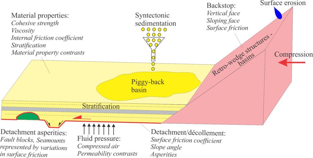
There is no shortage of published sandbox experiments over the intervening 30-40 years (from the Davis et al., models) that expand the concepts, methodologies, and analytical techniques initiated by these early pioneers. Graveleau et al., (op cit) have made a valiant effort to capture as many of these papers as is practicable (they cite a seemingly endless supply of papers). Many of the more recent studies have focused on specific aspects of sandbox mechanics and kinematics, particularly the effects of model boundary conditions such as:
- Surface friction coefficients on the stationary or movable base (detachment), and the backstop.
- The backstop slope (vertical or inclined) and orientation relative to the wedge strike.
- The stratigraphy of the wedge fill.
- Viscosity, density, and permeability contrasts of the wedge fill.
- Backstop convergence rates and strain rates within the wedge.
A plethora of experiments conducted over the last few years have attempted to answer important questions such as (I list here only a smattering of examples):
- How do variations in basal friction along the detachment (décollement) affect variables like critical taper? For example, low friction coefficients equate to lower taper angles; high basal friction produces thicker (higher) wedges (e.g., Bose et al., 2009).
- Do asperities on the detachment influence external or internal wedge structure? This is an important consideration for accretionary wedges where structures such as volcanic seamounts (part of the down-going slab) can influence the stress fields in the upper plate. Bose et al., (2015, PDF) modeled the influence on accretionary prism structures caused by horsts and grabens identified in reflection seismic profiles in the subducting slab beneath Japan Trench. They modeled these effects by varying the frictional resistance along the basal detachment.
- How do variations in fluid pressure along the detachment and within the wedge affect structural development? Variable fluid pressures were central to experiments conducted by Mourgues and Cobbold (2006, PDF); elevated fluid pressures were induced using compressed air through the base of the wedge. They showed that at low fluid pressures the wedge steepened beyond critical taper, becoming shallower at elevated pressures. They also showed that pressure gradients and permeability contrasts among a layered wedge-fill are important determinants of thrust and detachment geometry.
- Most early sandbox experiments used dry sand as the wedge material. What is the influence of more ductile materials such as silicone putty or paraffin wax on fault and fold development and wedge geometry? Do changes in strain partitioning caused by interlayering of non-cohesive and cohesive-viscous materials better represent thrust-related folds across ramp flats and fault tips? Experiments that incorporate materials having different strengths and viscosities can produce fault-fold pairs rooted in the main detachment and in secondary detachments at structurally higher levels in the wedge. Experiments like these can also build thrust duplexes.
- The backstop interfaces in early experiments were mostly orthogonal to the detachment. They were also assumed to be much stronger than the deforming wedge rocks (e.g., granite intrusions, metamorphic core complexes). Weaker backstops may become involved in the deformation. Lower indenter slopes that dip towards the foreland result in wedge materials overriding the backstop surface, that some experimenters call the retro-wedge. Friction across the indenter slope will also influence retro-wedge geometry. Along-strike backstop thickness and taper variations were investigated by Soto et al., (2006, PDF) who show in their models the effect on the propagation of wedge deformation fronts and thrust polarity, comparing their results with structural development in the Pyrenees.
- Experiments have also dealt with variable backstop convergence rates and oblique convergence, where it is possible to generate extensional and strike-slip structures that are mechanically linked to thrust faults (for example relay ramps). In these experiments, obliquity is generated either by changing the shape of the indenter (the actual push from behind remains orthogonal), or by rotating the indenter. For example, Leever et al., (2011, PDF) show that oblique convergence can influence fault dip and produce rotation of shears during initial strain partitioning. The addition of viscous, low-density materials like silicone putty or paraffin wax to the base of a model can to some extent simulate flow and isostatic adjustment as wedge loading increases.
- In many sandbox models the structural development of a wedge also generates excessive topography because there is no simulated erosion or isostatic adjustment, or because density scaling was incorrect.
- Sediment flux is generally modeled in one of two ways – either as sediment input to the wedge top, or removal by erosion. In terrestrial and shallow marine settings, sediment is derived by erosion of the backstop or hinterland and distributed to wedge-top basins (piggy-back basins) that are linked to drainage systems. Structurally elevated parts of the wedge may also be eroded. In some settings, carbonates may form in situ. Sedimentation on oceanic accretionary prisms is dominated by pelagic and hemipelagic deposits, plus any terrestrial material that can bypass the volcanic arc or backstop. Volcaniclastic contributions can also be significant. The addition of sediment to analogue models is usually done by sifting sand or coloured materials to the deforming wedge surface. This is particularly useful for monitoring both mechanical and kinematic changes in surface topography and fault propagation.
- Addition and removal of material also changes the overall wedge geometry(e.g., Soto et al., (2006, op cit, PDF). The addition of sediment potentially increases the wedge slope beyond the critical taper at which point strain will be transferred to the detachment; the opposite effect occurs with erosion. In real systems there is a balance between sediment accumulation and erosion; analogue models can successfully show how this balancing act changes with time.
Other posts in the modeling series
Geological models: An introduction
Model dimensions and dimensional analysis
