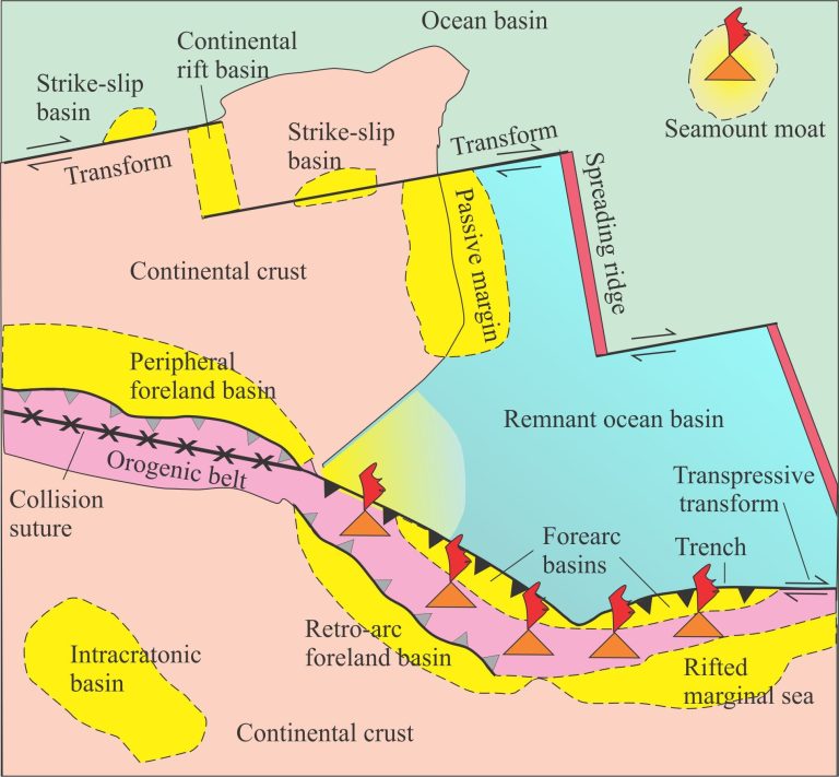
Here is a brief description of a submarine channel complex in the Jurassic Bowser Basin (northern British Columbia), a major foreland-style basin that overlies Stikinia terrane (underpinned by older arc volcanics) and records Stikinia’s accretion to Cache Creek Terrane (an ocean basin). Both Stikinia and Cache Creek terranes are part of Intermontane superterrane (composite terrane)in the Canadian Cordillera (see Ricketts 2019 for a general synthesis of Cordilleran basins.
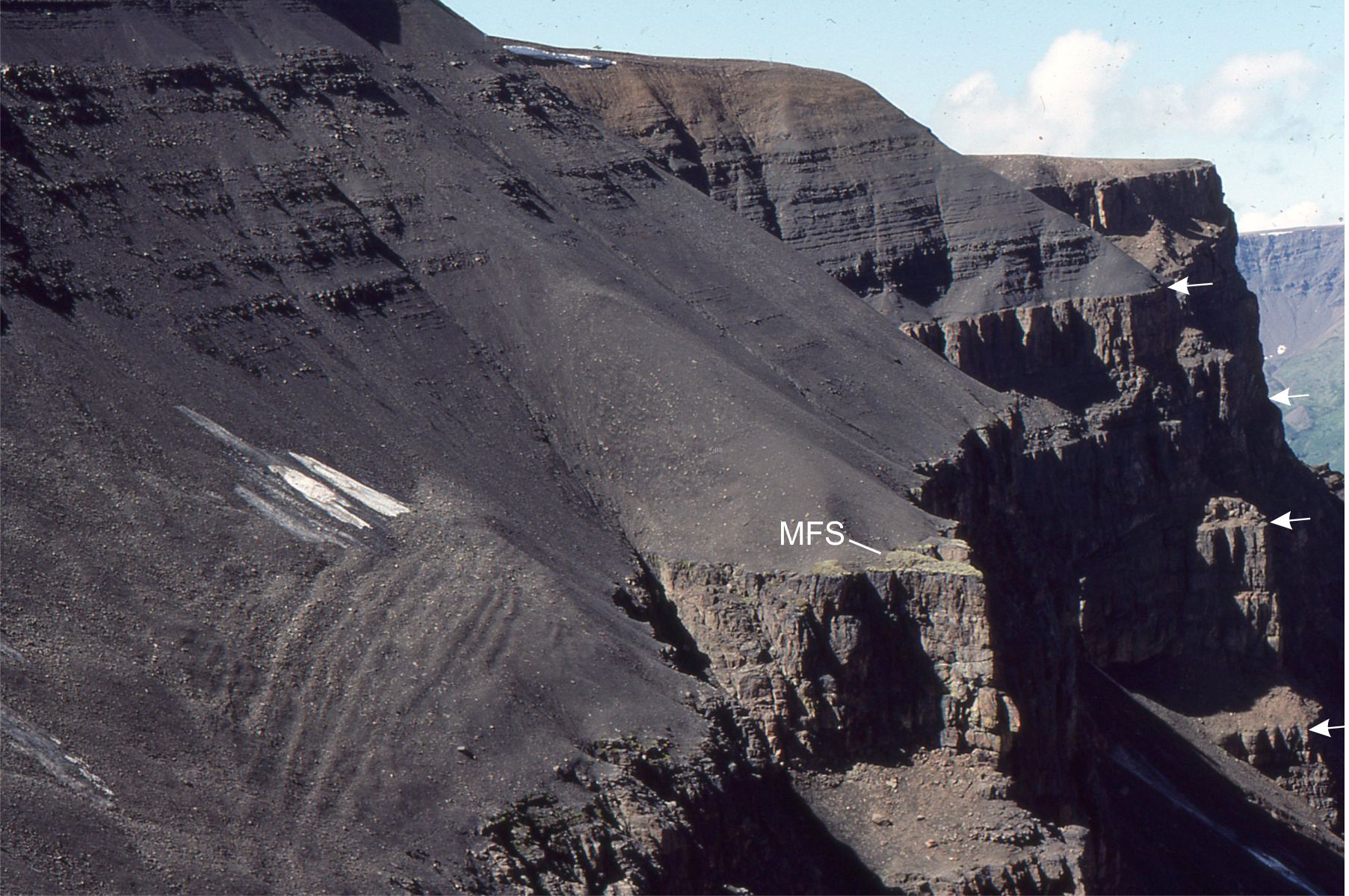
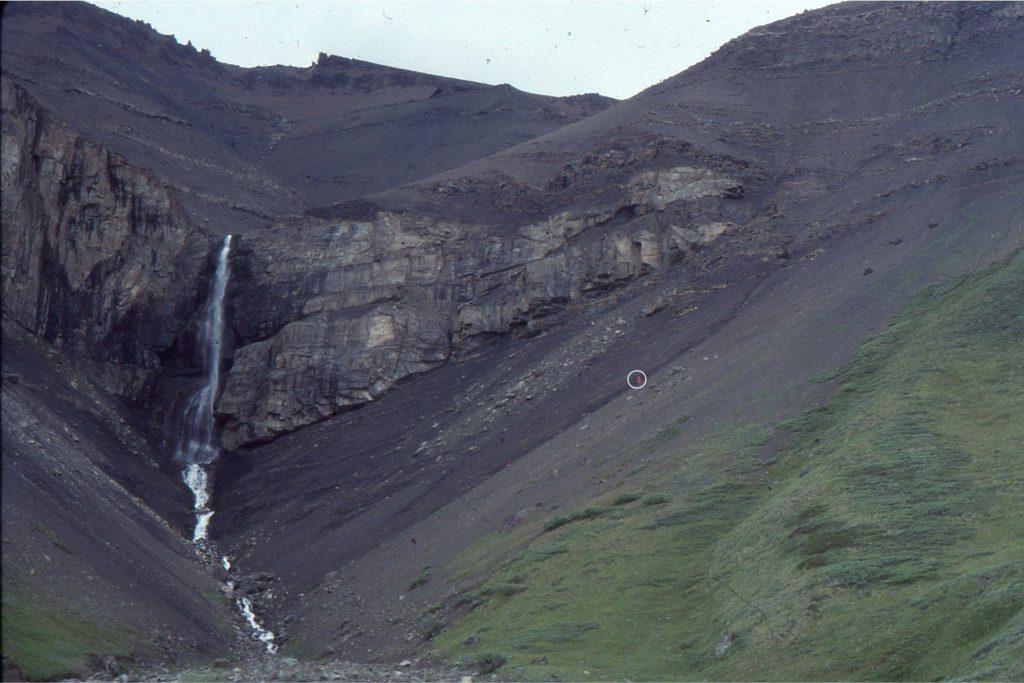
Stacked submarine channels were constructed on and incised into slope mudrocks. The composite channel thickness is about 300 m. The width of the complex is 1500-1800 m – the exposure is oriented close to depositional strike and therefore the channel cross sections approximate true width. Channel fill is predominantly bedded conglomerate and subordinate graded sandstone beds; beds range from 0.5 to 6m thick, although some of the thickest units may be composite. The conglomerates were deposited as debris flows where, at one end of the flow rheology spectrum, pebbly mudstones formed from cohesive, viscous muddy torrents, and at the other end of the spectrum clast-supported units from more mobile flows. The channels acted as conduits for gravel and sand supply to submarine fans. Conglomerate clasts are predominantly radiolarian chert derived from delaminated and overthrust oceanic Cache Creek Terrane.
Channel contacts are most easily identified where there is an abrupt transition to mudrocks and thin graded sandstone beds. However, walking out some of the contacts shows that the intervening mudrocks may pinchout and where this occurs the distinction between successive channels succession is difficult. This is particularly evident in the very thick part of the conglomerate succession (that forms the main bluff). For the complex as a whole there is a general sense that channel thalwegs migrated to the right – we can see this where the channel margins step to the right as we progress upwards through the aggradational stack.
Shelf edge gullies probably acted as conduits to the slope channels. Sediment was fed from a relatively narrow shelf, mostly during sea level lowstands but also at times of rising sea levels when sediment supply rates exceeded sea level rise because of hinterland uplift and active faulting. At some localities fan deltas prograded across the shelf, eventually spilling gravel and sand through the gullies.
Here are the links to some recent, excellent papers on submarine channels, from which I have taken some of my cues: Covault, 2011 for a review (open access); Deptuck and Sylvester (2018, PDF available); Jobe et al., 2020, open access; Palm et al., 2021 (channel widths).
A Aggrading channel stacks
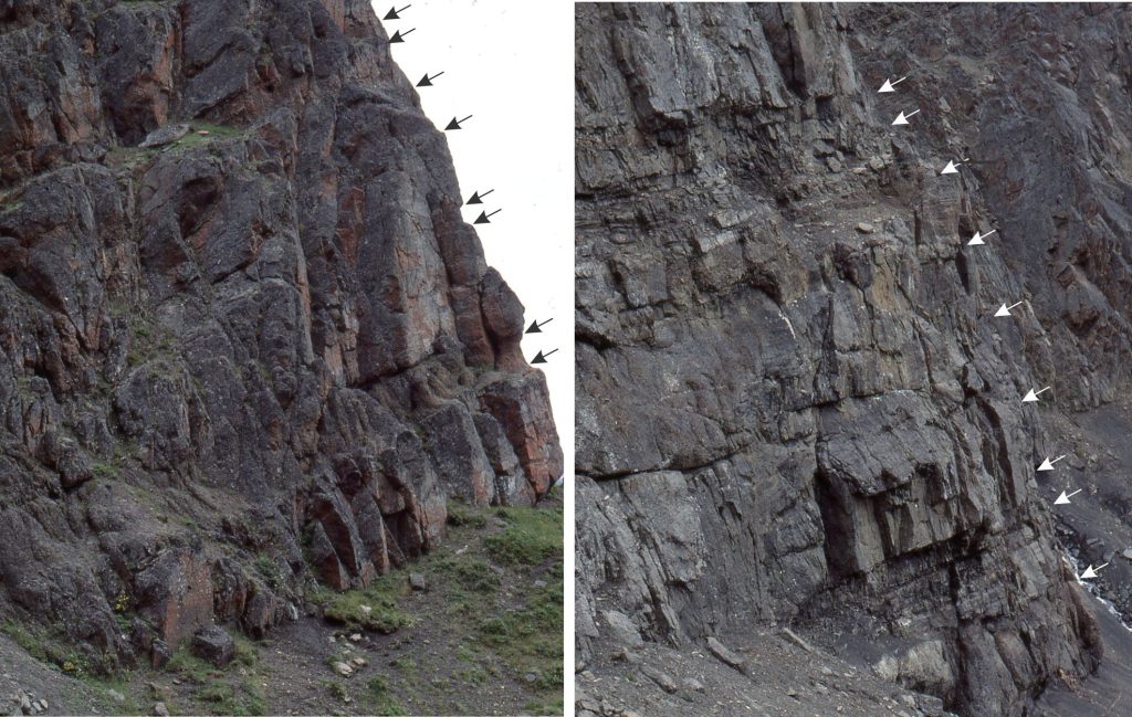
Two exposures near the base of the main channel complex contain a decent selection of muddy, cohesive debris flows and clast-rich, more fluidal debris flows. Arrows indicate flow units. Some flow units are separated by mudrock and thin sandy turbidites; others are stacked without intervening mudrock (in this case the shale-sandstone interbeds may not have been deposited or were removed by the subsequent flow). About 8 m of stratigraphy is shown in both.
B Channel pinchout and overbank
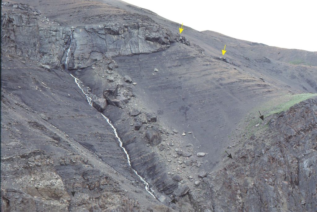
The top of the main channel complex is an abrupt and locally discordant contact that truncates the uppermost flow units (black arrows). Similar erosional truncations at other locations contain associated slump blocks. Slump-discordant contacts are a common feature of these slope channels and associated shelf-edge gullies. The overlying channel pinches out to the right. Isolated pods of pebbly mudstone extend to 50 m beyond the pinchout (yellow arrows) – these are interpreted as overbank surges.
The intervening mudrocks contain structures typical of hemipelagic deposition on continental slopes: laminated shale, turbidites a few mm to cm thick that display varying transitions from B through E Bouma divisions, thin rippled sandstone beds, small synsedimentary faults, convoluted bedding, slumps ranging from centimetres to 10s of metres thick (the larger deformed packages constitute mass transport deposits), sedimentary boudinage, and a restricted trace fossil assemblage dominated by Chondrites.
Slump or levee discordance?
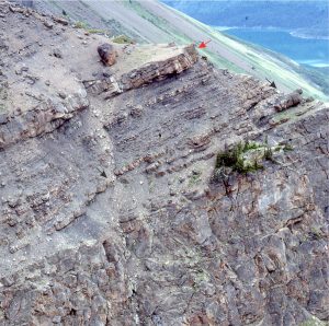
The angular discordance in the shale-turbidite unit above the main channel (black arrows) may have resulted from local slumping, or deposition over a channel levee. About 2 m above the contact is a pebbly mudstone containing left-dipping stratification that may be part of a levee (red arrow). This exposure is rather precipitous so we couldn’t check it out any closer.
D Abrupt channel margins
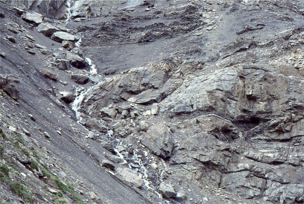
This channel margin is almost vertical and cut into slope mudrocks (the rivulet corresponds closely to the contact). The channel fill here is composite, with two main units separated by a thin bed of shale (arrows). The shale was partly eroded by the upper flow unit.
Many submarine channels contain meandering thalwegs that behave in a manner analogous to their fluvial counterparts. Their behaviour includes downstream migration of meander loops, channel margins where flow is deflected against a cut-bank, or constructional margins where flow provides sediment for accreting point bars. Channel levees constructed by overbank spillage are a common feature. Channels will also shift by avulsion that is caused by the erosive impact of large flows or slope instability.
In this example, the abrupt channel margin is interpreted as the cut-bank on a meander bend. Compare this with the example at location B that probably represents a more accretionary channel margin.
A couple of examples of the debris flows
Fluid, non-cohesive debris flows
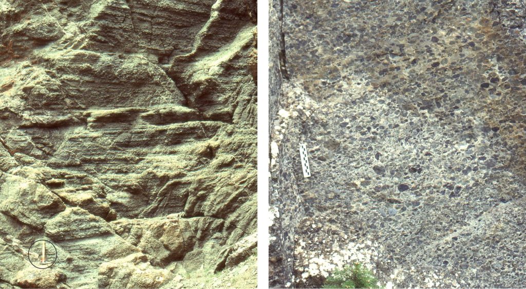
Typically, these flows have clast-supported frameworks and clasts may show crude imbrication. The matrix content is much lower than in the pebbly mudstones (below). Layering within flow units is common and is pronounced in the left image where the section is more than 6 m thick. Clast support was derived mainly from collisions during flow, aided by some matrix cohesion. Both the layering and imbrication indicate shearing within the body of the flow, possibly resulting from surging.
Cohesive muddy debris flows
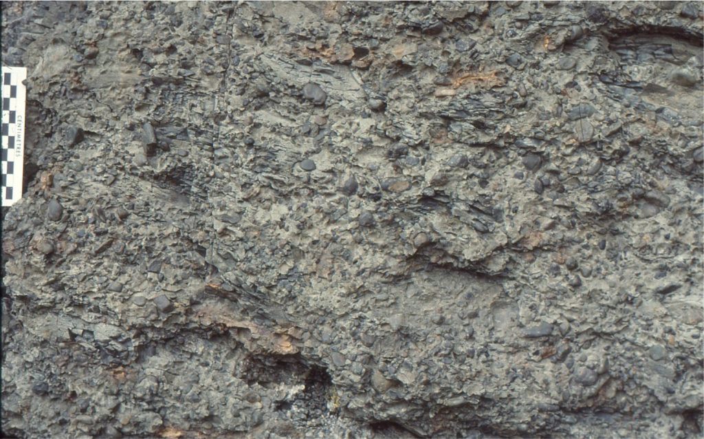
These flows are significantly more viscous than their clast-supported cousins. Typically they present as mud-supported clast frameworks, non- or poorly graded through the bulk of each flow unit but may show reverse grading at their bases. Mud rip-ups are common. The ability of the flow to support clasts of varying sizes was derived primarily from the cohesive strength of the mud matrix.
Other posts in this series
Sedimentary basins: Regions of prolonged subsidence
The rheology of the lithosphere
Isostasy: A lithospheric balancing act
The thermal structure of the lithosphere
Classification of sedimentary basins
Stretching the lithosphere: Rift basins
Nascent, conjugate passive margins
Thrust faults: Some common terminology
Basins formed by lithospheric flexure
Basins formed by strike-slip tectonics
Allochthonous terranes: suspect and exotic
Source to sink: Sediment routing systems
Geohistory 1: Accounting for basin subsidence
Geohistory 2: Backstripping tectonic subsidence
