The mystery of groundwater flow solved!
Groundwater is always on the move. Under some conditions, in fractures or other large conduits, it can move quickly; almost at a walking pace. Under other conditions it moves inexorably slowly, like fractions of a millimeter a year. Regardless, it is always compelled to move. Movement requires energy. Where does this energy come from? What drives the flow of groundwater? Answers to these questions provide the foundations to the science of hydrogeology.
Like any part of a youth misspent, I occasionally transgressed. In those rare moments of desperation for gasoline (for my aged car), I would siphon fuel from my parents’ vehicle. My conscience always got the better of me so I paid them back. But I expect they were annoyed. The process of petrol transfer was very straight forward; a short piece of hose, one end inserted into their petrol tank, the free end in my container. Suck on the free end to initiate the flow (the drawback to this method should be obvious), and hey presto. It always worked so long as the free end of the hose was lower than the business end. I doubt I gave it much thought at the time, but the siphon method is a great illustration of the importance of hydraulic head.
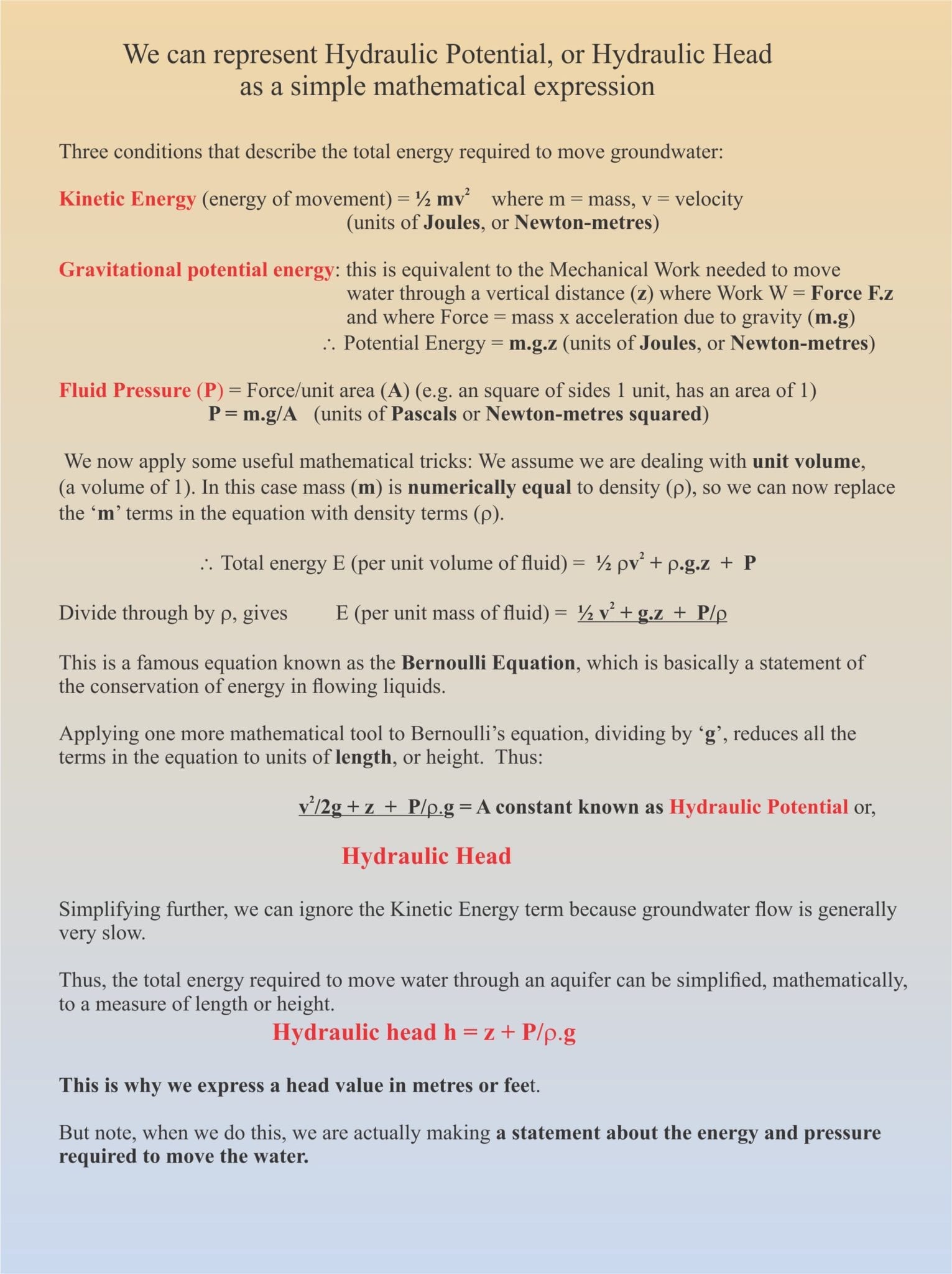
We need to consider three conditions to move a fluid through a siphon hose, or an aquifer, conditions based primarily on Newtonian mechanics: potential energy due to gravity, kinetic energy (the energy of movement), and the pressure from the surrounding fluid, or fluid pressure. The total energy can be expressed in an equation that sums these three components. The text box below shows the maths involved in deriving a simple expression for hydraulic head (if you don’t like the maths, just read on).
In 1738, Daniel Bernoulli published a thesis on the dynamics of fluid flow. In this, he developed an equation, the Bernoulli Equation, as a statement of the energy requirements for fluid flow. Bernoulli’s work can be applied to different kinds of fluid, but in groundwater we can take its simple form because water, for all practical reasons, is incompressible (more complicated forms of the equation are required for compressible fluids, like air). As shown in the text box, we can also ignore the kinetic energy component because the speed of groundwater flow is (usually) very slow. Thus, the final form of the equation, that describes hydraulic potential, or hydraulic head, is
Hydraulic head h = z + P/ρ.g
The units of ‘h’ are in length, commonly quoted as metres or feet. However, when we quote a head value, it is important to remember that we are making a statement about the energy and pressure requirements for groundwater flow. This statement of hydraulic head is fundamental to groundwater studies.
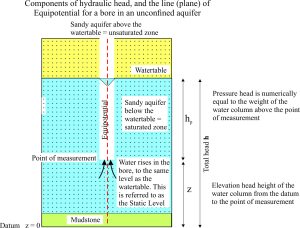
The expression for hydraulic head has two components: an elevation head (z), and a pressure head (usually designated hp). The diagram below shows the relationship between these two components, relative to some datum (a starting point for measurement); sea level is a common datum, in the same way that topographic elevations are referenced to sea level. But a datum can be any point of reference.
The dashed red line through the bore and extending to the datum, is called an Equipotential (it is actually a plane). The total hydraulic head is the same at any point on this line (or plane in 3 dimensions). However, the elevation and pressure heads change. In the diagram, the point of measurement is taken at the bottom of the bore (the water intake), and the two head components are indicated. If we choose the point of measurement at the watertable, then the total head would be equivalent to the elevation head alone; pressure head in this case would be zero. The opposite is the case is we choose to measure the head components at the datum – here elevation head would be zero.
Identifying equipotential lines, or planes in different parts of an aquifer is one of the most important tasks for hydrogeologists, because they allow us to characterize many aspects of groundwater flow. We can:
- Create contour maps of the distribution of total head, or either of its two components,
- determine hydraulic gradients,
- map the intersection of equipotentials with other water bodies such as rivers and lakes,
- predict and map the movement of contaminant plumes in groundwater,
- predict groundwater flow velocities; this is particularly important for predicting the movement of a groundwater contaminant.
Our siphoning ‘experiment’ makes use of the fact that fluids will flow from higher to lower hydraulic heads. For the siphon to work, the receiving container must be lower than the tank being drained. The same concept applies to aquifers, where groundwater will flow to locations of decreasing total head. Indeed, elevation differences, or topography, are the primary drivers for groundwater flow.
The utility of equipotentials will be the subject of a subsequent post.
Here are some other posts dealing with groundwater:
Whiskey is for drinkin’; water is for fightin!
The Architecture of Connected Holes; A Different Way to Look at the Liquid Earth
“My water well taps into an underground river” and other myths
