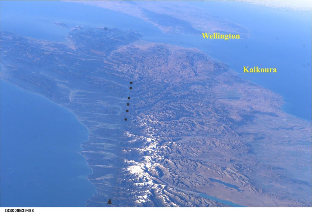
In 1940 Harold Wellman and Dick Willett proposed that two groups of rocks at either end of the South Island of New Zealand, each having the same stratigraphic and lithologic characteristics, were at one time a single unit. The dislocation was the result of 600 km lateral shift along a major fault. This was pre-plate tectonics. The consensus at the time was that crustal movements were dominated by vertical displacements. Wellman’s hypothesis turned a few heads and invited its share of derision. But he was right… Jumping ahead a few years (and encapsulating several decades of science history in a single sentence), we now know this fault as the Alpine Fault, a dextral, or right-lateral transform strike-slip fault that also doubles as the boundary between the Pacific and Australian plates.
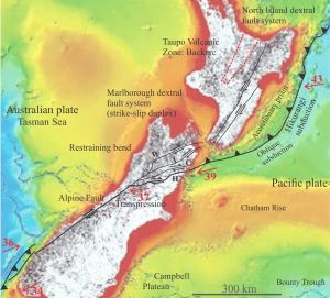
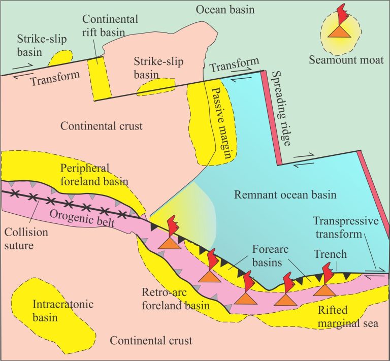
Strike-slip faults occur in most plate tectonic settings, primarily at plate boundaries (like most other fault types). They form in oceanic and continental crust/lithosphere. The characteristic zig zag dismembering of mid-ocean spreading ridges is caused by ridge transforms that accommodate the strain from oblique spreading. Convergent margins with oblique plate trajectories will also generate strike-slip faults in accretionary prisms, forearcs and backarcs.
Our understanding of strike-slip faults has advanced with detailed field mapping, subsurface imaging, and numerical and analogue modelling. Strike-slip faults do not occur in isolation; they come with a bevy of subsidiary structures that reflect the associated extensional and contractional stresses. In fact, it is these “minor” structures that frequently allow us to decipher the tectonic and kinematic history of such faults.
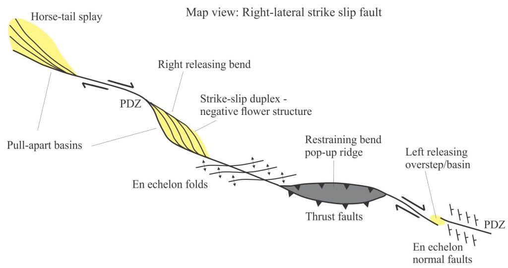
Common strike-slip structures are illustrated in the following diagrams and definitions. Most have been borrowed and modified from important papers and texts on the subject: Biddle and Christie-Blick, 1985 (Intro to SEPM volume – PDF available); Sylvester, 1988 – (PDF); Nilsen and Sylvester, 1999 (PDF); Davis and Reynolds, 1996 (an excellent text); Allen and Allen, 2005, 2013.
You are invited to look at two other posts on faults – Thrust faults, and more general Terminology of faults. There is a companion post of Basins formed by strike-slip tectonics
Some common definitions
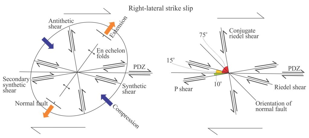
Antithetic faults: Subsidiary or minor faults that have a sense of displacement opposite that of a master fault or principal deformation zone. They occur in extensional regimes (such as accommodation in the hanging wall of listric faults), compressional regimes as back-thrusts, and strike-slip faults. Opposing subsidiary structures are synthetic where the displacement has the same shear sense as the master fault. Antithetic and synthetic faults commonly occur in parallel arrays. Cf. Riedel shears.
Conjugate Riedel shears: See Riedel shears.
Conjugate faults: Fault pairs where the fault planes intersect at (commonly) 60o such that the direction of minimum extension bisects this angle, and the direction of maximum extension bisects the obtuse angle (~120o). Conjugate faults occur in dip-slip and strike-slip structural domains.
En echelon folds: Anticline-syncline pairs that in an ideal system will be about 45o to the PDZ. Fold axes parallel the long axis of the strain ellipse – the axis of maximum extension, and bisect the angle between Riedel and conjugate Riedel shears. Fold axes will also be at right angles to extensional normal faults.
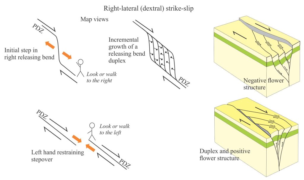
Flower structures: Characteristic fault splays that develop at restraining and releasing bends, and at stepovers of strike-slip faults. Strain is concentrated at these locations along the fault plane so that movement along the main fault is transferred to a secondary fault; this process can be repeated several times, producing fault splays that in 3-dimensions, merge with the master fault. These splays are also called strike-slip duplexes. Flower structure refers to the cross-sectional view of duplexes. In positive flower structures (also called palm tree structures), the displacement is predominantly reverse (transpressional); in transtensional environments the displacement is normal dip slip in cross-section – these are negative flower structures or tulip structures. However, the sense of displacement can change up fault plane dip and along strike.
Normal faults/Tension gashes: Normal faults are expected at releasing bends and stepovers. On the strain ellipse, fault plane strike is normal to the axes of en echelon folds and parallel to the compressional axis.
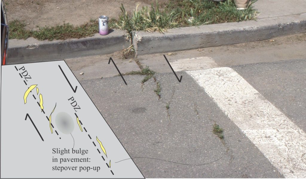
Principal displacement zone – PDZ: The zone or plane of dip-slip or strike-slip that accounts for greatest proportion of accumulated strain. Subsidiary structures such as synthetic and antithetic faults and folds (e.g., fault splays, back-thrusts, fracture zones, en echelon folds) will be kinematically linked to the PDZ.
Releasing bend: Strike-slip motion at a bend in the PDZ that produces extensional structures. Pull-apart, or strike-slip basins are commonly developed at releasing bends. The left or right handedness of bends is determined by looking along the trend or strike of the fault – if the bend moves to the left, it is a left bend. Thus, a full description of the fault bend might be left-handed/releasing/sinistral or left-lateral strike-slip fault. Cf. Restraining bend, stepover.
Restraining bend: Strike-slip motion at a bend in the PDZ that produces compressional structures such as thrusts and pop-up ridges. The left or right handedness of bends is determined by looking along the trend or strike of the fault – if the bend moves to the left, it is a left bend. Cf. Releasing bend, stepover.
Ridge transform: Transform faults that segment oceanic spreading ridges; they accommodate oblique spreading. Associated ridge fracture zones represent inactive ridge transforms.
Riedel shears: Parallel arrays of faults that form during the early stages of strike-slip formation. They are oriented at low angles to the principal displacement zone, commonly about 15o, and are synthetic to the PDZ. As deformation continues the Riedel shears become linked and part of the PDZ. A second set of faults at about 75o to the PDZ are conjugate to the Riedel shears and antithetic to the PDZ. The line bisecting the conjugate set parallels the direction of principal stress (on a strain ellipse this is the long axis); it also parallels the axes of en echelon folds. A third set of shears, P shears, at 10o and less to the PDZ, may form after the Riedel shears, and link with them to form the PDZ.
Stepovers: A stepover occurs where the strain at the end of one fault is transferred to the beginning of a parallel fault having the same sense of displacement. Stepovers can be restraining or releasing. They are also described as left or right in the same way that bends are described; at the end of one fault, you look right or left to find its parallel accomplice. Pull-apart basins and pop-up ridges can also form at stepovers depending on whether they are restraining or releasing.
Strike-slip/pull-apart/wrench basins: Elongate, rhomboid- or sinusoidal-shaped basins formed at releasing bends and stepovers of strike-slip faults. They are relatively small basins compared with passive margins and foreland basins, but they have high aspect ratios – depth to areal extent and can accommodate many kilometres of sediment fill. Sediment composition may change over the life of a strike-slip basin because of lateral shifts in source rock.
Synthetic faults: See antithetic fault
Tear faults: These faults basically accommodate differential movement or strain within large fault blocks. They occur mainly in normal and reverse-thrust fault systems.
Transcurrent faults: Major strike-slip faults that are generally confined to thin-skinned crustal deformation. Cf. Transform faults.
Transfer faults: Strike-slip faults at various scales that transfer dip-slip motion from one fault block to another. They are common in extensional-rift regimes and thrust systems.
Transform faults: Strike-slip faults that form plate boundaries, and therefore extend through the lithosphere. They can form in continental lithosphere (e.g., San Andreas Fault in California; Alpine Fault in New Zealand), or oceanic lithosphere (ridge transforms). They are kinematically linked to and terminate at other plate boundaries – spreading ridges, subduction zones, or other transforms.
Transpression: A combination of strike-slip (dominant) and convergence developed at convergent plate boundaries.
Transtension: A combination of strike-slip (dominant) and extension; also called oblique slip. Most major strike-slip faults have a component of transtension or transpression. Transtension is developed at divergent plate boundaries (continental or oceanic rifts) and extensional components of orogenic belts.
Other posts in this series on Common Structure and Mapping Problems
Solving the three-point problem
Stereographic projection – the basics
Stereographic projection of linear measurements
Stereographic projection – unfolding folds
Stereographic projection – poles to planes
The Rule of Vs in geological mapping
Using S and Z folds to decipher large-scale structures
Cleavage and cleavage-bedding intersections
The kinematics of deformed rock
Faults: Some common terminology
Accretionary prisms and forearc basins
